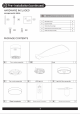
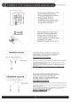
&, HARDWARE INCLUDED components table i A Mounting sees “4 BE | Essen Bas 2 £6 | Deadpanned pancake ARE OR HER BEL dtl noi bn snail 5 A Fan-moor assembly 11B1 Blade 3 Oo Farmer assembly 1 Db LES Hahn ALE Light killer assembly 1 ART 5 sil FE Glass lampshade TE] Renowsmundmsaine 1H] Ree SRE | vat 1
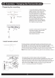
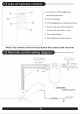
dD Assembly — Hanging the Fan{continued) Preparing for mounting 4 Use Rita sniffle box stables for fan support and ise only the screws provided i Install remote control with the fortieth box Faust support.
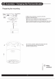
dD assembly — Hanging the Fan(continued) Preparing for mounting 5 Make wiring conjunctivas using interconnections provided as indicated shove. White from house-to White from remote receiver marked AUN, Black from house 10 Black from remote marked ACL. Inertial green grounded Wis Yo Grounding wire tom House, Wake site that no laments Ge offside of the Wire Connector, G.Lift motor assembly, aligning the keyhole slots with the reassembled screws on mounting plate, and twist clockwise tI lock.
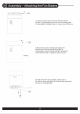
Q@, Assembly — Attaching the Lights 1. Install the light kit fitter, tighten all screws. 2. Connect the light kit with motor, put the light kit in the light kit fitter. 3.
QD.
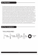
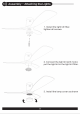
HITTITE Put the clip in the center of a blade. turn on the fan and if the shake persists, put the clip in another blade until the shake is reduced. Then this blade will need the counterweight. Place the clip on the blade that needs the counterweight and try the best place fo place it, from the center to the tip of the blade, until the wobble disappears. Paste the counterweight on the surface of the blade which near the clip, remove the clip and test the fan. If it keep staggering, put another counterweight.