V1.98 21/06/06 X20/X15/X10 Operators Manual Spray Rate Control A2677 V1.98 1.4 .
V1.98 V1.98 21/06/06 21/06/06 As with any computer operated equipment, software and/or hardware is in many cases changed and upgraded over the life of the equipment. KEE Technologies software engineers are constantly working on software enhancements which will provide you with many additional benefits and features in the future. The ZYNX System will keep on evolving! ...
Contents V1.98 21/06/06 V 1.86 Content Page No. Introduction How to Use this Manual 6 7 INSTALLATION 1.0 1.1 1.2 1.3 1.4 1.5 For ALL Installations and Servicing of Spray ECU’s Installing the Spray ECU (All Models) Installing Spray ECU 30S KEE Spray Controller Kits 1.2.1 Installing the Tractor Harness 1.2.2 Installing the Sprayer Harness 1.2.
Contents V1.98 21/06/06 21/06/06 V1.98 V 1.86 Content Page No. SETTING UP THE SPRAYER 17.1 17.2 17.3 17.4 17.5 17.6 17.7 17.8 17.9 17.10 Pressure Window Calibrating the Pressure Sensor Manual Entry of Pressure Calibration Factors (Spray ECU) Flow Window Speed Window Area/Volume Window Tank Setup 17.7.1 Fill The Tank Calibrate The Flow Meter 17.8.1 Flow Calibration for Normal Valves 17.8.2 Flow Calibration for Balanced Valves Enable Lockout Feature 17.9.1 Enable Lockout 17.9.
Contents V1.98 21/06/06 WIRING CONNECTION TABLES 21.1 21.2 21.3 21.3.1 21.3.2 21.4 21.4.1 21.4.2 21.5 21.5.1 21.5.2 21.6 21.6.1 21.6.2 21.7 21.7.1 21.8 21.8.
Introduction V1.98 21/06/06 Major Topic Heading Introduction The Spray ECU is a new generation spray controller to used in conjunction with the NEW X20 or ZYNX X15 consoles brought to you by KEE Technologies. The Console is the graphical interface of the Spray ECU controller. The Spray ECU replaces the KEE Sprayrate Interface.
How to use this Manual V1.98 21/06/06 HOW TO USE THIS MANUAL All operators who have a Spray ECU installed must read the following page: Section 1.0 ‘For all Installations and Servicing of Spray ECU’s’. Upgrading the ZYNX Spray Rate Control Software If the ‘Spray Rate Interface’ or ‘Spray ECU’ is already installed and you are using this book to upgrade the ZYNX Sprayrate Control software to a later version, then go to straight to Section 3.0 ‘Configuration Setup’. Installation of the Spray ECU 1.
How to use this Manual V1.98 21/06/06 8. Section 16: ‘Saving the Configurations’ section shows the operator how to save and name the sprayer settings entered into the Sprayer Software Setup (Sections 4 to 15). 9. Section 17:’Setting up the Sprayer’ explains the Pressure, Flow, Speed, and Area/Volume windows. This section explains how to ‘Fill the Tank’ and the Sprayer Switchbox. This section also explains how to Calibrate the Pressure Sensor and Flow sensor.
V1.
Warning when Installing Spray ECU Controller V1.98 21/06/06 1.0 FOR ALL INSTALLATIONS AND SERVICING OF SPRAY ECU'S Damage will occur if any external power is applied to the Section Drive Outputs on the Sprayer ECU. Follow this procedure to ensure that damage is avoided. Disconnect both the ZYNX Console and Spray ECU controller from the battery before charging, jump starting or welding on the vehicle and/or sprayer.
Installing the Spray ECU V1.98 21/06/06 1.1 INSTALLING THE SPRAY ECU (ALL MODELS) Step 1: Installing the Spray ECU 30S Note: DISCONNECT THE VEHICLE BATTERY before proceeding with any installation or servicing of the Spray ECU 30S or Tractor harness. Before commencing any installation or servicing of the Sprayer Harness or Valve Harness, make sure the Tractor Harness is disconnected from the Sprayer harness. DAMAGE WILL OCCUR if any external power is applied to the Section Drive Outputs on the Spray ECU.
Installing the Spray ECU V1.98 21/06/06 6. Connect the Sprayer Switchbox, shown in Figure 3, to the '9-pin connector marked SWITCHBOX on the Spray ECU. Then mount the Sprayer Switchbox using the doublesided tape supplied or other suitable means. Mount the Sprayer Switchbox in a position which is easily accessible while spraying. Note: The Sprayer Switchbox can be used so, one switch, switches one boom section ON and OFF.
Installation of Spray ECU 30S KEE Sprayer Kits V1.98 21/06/06 1.2 Installation of Spray ECU 30S KEE Sprayer Kits All KEE Sprayer kits come with their installation guide which is specific to each kit, please use the specific installation guide which come with your KEE Sprayer kit. This section is a general guide for an installation of all KEE Spray ECU 30S Sprayer kits. This installation guide will take the installer through the following steps: 1.2.1 Installing the Tractor Harness 1.2.
V1.
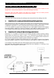
General System Layout for Spray ECU 30S KEE Controller Kits Dump Valve Tractor Harness Sprayer Loom Figure 5: General Sprayer and Valve harness assembly Page 15 V1.
Installation of Spray ECU 30S KEE Sprayer Kits V1.98 21/06/06 1.2.2 Installing the Sprayer Harness 1. The Sprayer Harness connects to the Tractor Harness at the back of the tractor or vehicle via the connector and continues across the sprayer's chassis to the valve set. Figure 5 shows the Sprayer Harness and Valve Harness Assembly. 2. Do not cut or splice the Sprayer Harness. Excess cable should be strapped away to avoid vibration and wear.
Installation of Spray ECU 30S KEE Sprayer Kits V1.98 21/06/06 2. Glue the magnets to the wheel studs with the side marked with a cross (+) facing the Shaft/Speed Sensor. Use any silicone or epoxy type adhesive allowing adequate time to set. Ensure that the magnets are spaced equally around the wheel to ensure accurate speed update. To ensure adequate speed update place magnets onto ALL of the available wheel studs. A Wheel Calibration Factor of no greater than 0.6m (24 inches) is required.
Installation of Spray ECU 30S KEE Sprayer Kits V1.98 21/06/06 Installation of a Shaft/Speed Sensor kit to a tail shaft 1. On a tray mounted sprayer the Shaft/Speed Sensor Kit can used to read from the vehicle tail-shaft. Refer to Figure 9. Using the Hose Clamp or other suitable means securely mount the Magnet Block on the flange between the transmission housing and the tail shaft. Note: Do not attach the Magnet Block directly to the tail shaft as its position changes through its rotation.
Installation of Spray ECU 30S KEE Sprayer Kits V1.98 21/06/06 Connecting to Flow Meter 1. The flow meter (not supplied) is installed between the regulator valve and the section valves. The flow meter will be installed so that it measures ONLY the quantity of liquid being delivered to the spray line. Note: There must be no return line to tank or pump after the flow meter. 2. Connect the flow meter 3-pin connector to the 3-pin connector marked Flow Meter 1 on the Sprayer Harness.
Installation of Spray ECU 30S KEE Sprayer Kits V1.98 21/06/06 Major Topic Heading Pressure Sensor installation and connection 1. Mount the Pressure Sensor (A092) either upright or horizontal and support the brass gauge saver. To properly measure Spray Line operating pressure the Pressure Sensor must be positioned between the flow meter and the section valves. The supplied Pressure Sensor is a 5 Bar (72 psi) pressure sensor. 2.
Installation of Spray ECU 30S KEE Sprayer Kits V1.98 21/06/06 Single Line Install 5. Connect the connectors marked Section X (‘X’ represents the section number) to the correct section valves. Section 1 connects to the section valve on the far left. Section 2 connects to the next section valve and so forth until all the section valves are connected to the Valve Harness.The section valve with the highest number will operate the boom section on the far right.
Installation of Spray ECU 30S KEE Sprayer Kits V1.98 21/06/06 9. Once all the ARAG connectors are in place, using a screwdriver tighten the screw at the top of the ARAG connector to secure the connector to the section and dump valves. 10. Tidy any excess harness using cable ties. 11. To complete the installation go to Section 1.5 to connect the Spray ECU Power/Comms harness to the battery.
Plumbing for Diaphragm Pumps for KEE Sprayer Kits Major Topic Heading Plumbing for Diaphragm Pumps for KEE Sprayer Kits Figure 10: Plumbing Diaphragm Pumps for KEE Sprayer kits Page 23 V1.
Plumbing for Centrifugal Pumps for KEE Sprayer Kits Plumbing for Centrifugal Pumps for KEE Sprayer Kits Figure 11: Plumbing for Centrifical Pumps for KEE Sprayer kits Page 24 V1.
Installing Spray ECU 30S Kits to Existing KEE Controller V1.98 21/06/06 1.3 INSTALLING SPRAY ECU 30S KITS TO AN EXISTING KEE CONTROLLER Note: Use this install guide if replacing an existing a KEE MK3, KEE MK5 sprayer console or KEE Sprayrate Interface. 1. 2. 3. 4. 5. 6. 7. 8. 9. Before removing the existing Controller Run the Sprayer and record the minimum and maximum pressure and flow rates attainable. Ensure that the system is functioning correctly before removing the controller.
General Layout of fitting a Spray ECU 30S to an Existing KEE Spray Controller Figure 12: General Layout of Spray ECU connecting to existing KEE Sprayer Harness Page 26 V1.
Installing Spray ECU 3 and Spray ECU 10SR V1.98 21/06/06 1.4 REPLACING EXISTING RAVEN CONTROLLER WITH A SPRAY ECU 10SR OVERVIEW The 10SR Spray ECU have been pinned to allow direct replacement of some of the Raven 4xx, 6xx, 4400 and 4600 series controllers. Generally most 4xx, 6xx and 4400 series controllers with inbuilt section switches can be replaced with no need for adaptors. Connector 1 is used for the 4400 series, Connector 2 for 4600 series and connector 3 for the 4xx and 6xx series controllers.
Installing Spray ECU 3 and Spray ECU 10SR V1.98 21/06/06 Digital Multimeter (DMM) Test Procedure 1. Testing voltage on section outputs on Raven Console Harness with switches on. With DMM set to 20vdc insert Gnd probe into Gnd Pin (usually Pin 1) and Positive probe into each section pin. Confirm yes or no to voltage present. 2. Testing for Gnd on section outputs on Raven Console Harness with switches off.
System Layout for Spray ECU connecting to an existing Raven console V1.
Connecting the Spray ECU to the Battery V1.98 21/06/06 Step 5: Connecting the Spray ECU to the Battery 1. DO NOT attach the wires to the battery terminals until the installation of the Tractor Harness, Sprayer Harness and Valve Harness has been completed. 2. Connect the Power/Comms Harness directly to 12 VDC battery terminals. Refer to Figure 14. For tractors that use 24 Volt batteries you MUST use a 12 Volt / 15 Amp (minimum) inverter. Figure 14: Battery Configuration 3.
Spray Rate Control 2.
Getting Started V1.98 21/06/06 2.1 STARTING THE X15 CONSOLE ‘SPRAY CONTROLLER screen ‘GUIDANCE’ screen ‘START’ button ‘STOP’ button Figure 15: ZYNX Product Selection screen 1) 2) 3) OR 4) Switch the ZYNX X15 Console ON Press the ‘SSTOP’ button when the ‘ZYNX X15 Product Selection Screen’ is displayed. Highlight the SPRAY CONTROLLER. (If the ‘Sprayer Controller’ software is being used on its own. Highlight the SPRAY CONTROLLER and GUIDANCE screens..
Getting Started V1.98 21/06/06 2.2 STARTING THE X20 CONSOLE ‘SPRAY CONTROLLER screen ‘GUIDANCE’ screen ‘START’ button ‘STOP’ button Figure 15: ZYNX Product Selection screen 1) 2) 3) OR 4) Switch the ZYNX X20 Console ON Press the ‘SSTOP’ button when the ‘ZYNX X20 Product Selection Screen’ is displayed. Highlight the SPRAY CONTROLLER. (If the ‘Sprayer Controller’ software is being used on its own. Highlight the SPRAY CONTROLLER and GUIDANCE screens..
Getting Started V1.98 21/06/06 Major Topic Heading ZYNX SPRAYER Logo OPTIONS button ZYNX ‘Sprayer Menu’ MAIN MENU button FIGURE 17: ‘SPRAYER WORKING SCREEN’ 2.3 REGISTRATION AND SPRAY RATE CONTROL SOFTWARE VERSION 6) The ‘WORKING SCREEN’ will be displayed, with the ZYNX ‘Sprayer Menu’ on the right-hand side. Press the ZYNX Sprayer Logo Icon, an ‘About ZYNX Spray Rate Controller’ window will be displayed, as displayed below.
Getting Started 2.4 V1.98 21/06/06 OVERVIEW OF FUNCTIONS- WORKING SCREEN Boom Sections (ON/OFF) - Up to 30 sections. Spraying Indicators for Back Line Main Menu Screen Front boom Back boom Ground speed Spraying Indicators for Front Line Sub total area Pressure Readout Sub-total of volume or weight used Tank Indicator (displayed if more than 1 tank is selected) Automatic Control Manual Control Volume Readout for each Tank Pump Speed Readout ‘Min.
Getting Started V1.98 21/06/06 Overview of Functions- The ‘Working Screen’ Boom Sections- Displays the number of boom sections selected. A ‘Dual’ boom is shown, showing the front and back lines; the top line representing the front line and the bottom line displaying the back line. If ‘Single’ line is selected in OPTIONS/SPRAYER then only a single line of sections would be displayed.
Getting Started V1.98 21/06/06 Major Topic Heading Overview of Functions- The ‘Working Screen’ ‘PUMP is ON’- button only appears when ‘Spray ECU’, ‘Prop. Valve’ and ‘Enable Pump Control Button’ are all selected. When selected the button says ‘PUMP is ON’ and turns ‘green’, this switches the hydraulic pump ON. When selected again the button says ‘PUMP is OFF’ and turns ‘red’, this switches the hydraulic pump OFF.
Navigating Around the Options Window V1.98 21/06/06 Major Topic Heading 2.5 NAVIGATING AROUND THE OPTIONS WINDOW From the ‘Working Screen’ select the ‘OPTIONS’ button, this will advance you to the ‘Options’ window. To explain the various options for navigating around the screen, the ‘Tanks’ and’ Sections’ pages will be used, as examples, as shown below.. An explanation of the terms used are explained on the following pages, this will help you select the right options for your sprayer.
Navigating Around the Options Window V1.98 21/06/06 Selecting- means selecting an item by ‘touching’ the screen with your finger (or mouse if connected to the ZYNX Console). There are various ways of selecting the different options. 1- To select a ‘Pr. Sense’ option, you would touch the screen either on the ‘white box’ or where ‘Tank 1’ is written, when selecting a ‘tick’ will appear in the box. 2- To select an option within the ‘Tank 1 Mode’ window, you would ‘touch’ the screen i.
Navigating Around the Options Window V1.98 21/06/06 Selection Options- Are options identified with white circles lying next to the written option. Examples of ‘Selection Options’ are ‘Tank 1 Mode’, ‘Lines’, and ‘Controller’ windows. With ‘Selection Options’ for that window, one and only one option can be selected. The option is selected when a black ‘dot’ is placed in the circle next to it. At least one of the options must be selected.
Navigating Around the Screen V1.98 21/06/06 Calculator Icon- The ‘Calculator Icon’ button, when selected, allows the operator to enter a value for the option for which is next to the ‘Calculator Icon’. The value next to the ‘Calculator Icon’ displays the current value for that option. Example, in the ‘Sections’ window, the current ‘Number’ of sections is ‘8’, to change the number select the ‘Calculator Icon’ next to the ‘Number’.
Configuration Setup V1.98 21/06/06 Major Topic Heading 3.0 CONFIGURATION SETUP Audio Volume Slide Displays the name of the ‘Current Configuration’. Note: No configuration is currently loaded. Figure 25: Options- Configuration page 1) Select OPTIONS from the ‘ZYNX SPRAYER’ MENU on the right hand of the screen. A Configuration window will be displayed, as shown above. Complete the installation of the Sprayer before setting up the ZYNX Sprayer software.
Configuration Setup V1.98 21/06/06 Major Topic Heading 3.3 FACTORY CONFIGURATION The ‘Factory Configuration’ button allows selection of KEE Sprayer kits or Listed Sprayers 1) Select ‘Factory Configurations’ button. A ‘Select File’ window will be displayed, as displayed below. Check to see whether your Sprayer or KEE Sprayer kit is listed here. 2) 3) 4) If your sprayer is not listed then go to ‘Point 3’. If your sprayer is listed then go to ‘Point 5’. Select the ‘CANCEL’ button.
Configuration Setup V1.98 21/06/06 Major Topic Heading 3.4 QUICK SETUP Once a Sprayer or Sprayer kit is selected then the most of the sprayer values and settings will be loaded into the ZYNX Sprayer software OPTIONS and the operator will only have to enter a few values to get started. For Example: Section Widths, select the type of Units (metric, imperial etc), Flow Sensor Calibration factor, Wheel Calibration Factor, to be used etc.
Spray Rate Control 4.
Sprayer Software Setup -GPS 4.0 V1.98 21/06/06 GPS Figure 28: Options- GPS page Note: the GPS Page is only displayed when Guidance and OR ‘Variable Rate Control’ (VRC) is selected with ‘Spray Rate Control’, when selected from the ‘ZYNX X20 Product’ screen . Otherwise the ECU page will be the first page. Auto Section Control (ASC) ‘Auto Section’ can only be selected when a DGPS is used in conjunction with ZYNX Guidance.
Software Setup Options -GPS V1.98 21/06/06 VRC/Log Synchronization Note:This window will appear if ‘Logging Only’ or ‘VRC and Logging’ are selected in the ‘VRC/Logging Mode’ window. 1- ‘OFF’- select this option if you want to be able to switch the ‘Treatment’ button ON and OFF in the VRC (Maplink) screen, independently of the Sprayer Master switch. 2- ‘Master Switch Only’- select this option for the Logging in the Variable Rate Control (VRC) to follow the Master Switch. Therefore Master ON- Logging ON.
Software Setup Options-ECU 5.0 V1.98 21/06/06 ECU (Electronic Control Unit) Figure 29: Options- ECU page Controller Note: See Section 20 to select the correct controller, if unsure. Select ‘Spray Interface’ if one of the following is written on the spray controller: 1- KEE Sprayrate Interface 2- ZYNX 5500 Interface 3- ZYNX 2500 Interface OR Select ‘Spray ECU’ if ‘SPRAY ECU’ is written on the Spray Controller. Select the correct controller.
Setup Options-ECU V1.98 21/06/06 Major Topic Heading Speed From Select from one of the 3 options; ‘Wheel Sensor’, ‘Tractor Radar’ or ‘GPS Speed’. Depending on whether ‘Spray Interface’ or ‘Spray ECU’ was selected in the ‘Controller’ options. ‘Spray Interface’ 1- Select ‘Wheel Sensor’ if a ground speed sensor is connected to the spray harness plug marked ‘Wheel Sensor’, usually located on the ‘Spray Harness’. 2- Select ‘Tractor Radar’ if connecting a Tractor Radar to the ‘Spray Interface’.
Setup Options-ECU 5.1 V1.98 21/06/06 ECU (Spray ECU only) Figure 30: Options- ECU page (Spray ECU only) ECU Configuration The ‘ECU Configuration’ window, in Figure 30 will only be displayed when ‘Spray ECU’ is selected as the Controller. ECU Model Select ‘ECU, ECU3’ option if the description on the overlay reads either ‘SPRAY ECU’, ‘SPRAY ECU 3’ or ‘Hardi 5500 SPRAY ECU’. The corresponding part number on the Spray ECU is either A2036, A2445 or A2243.
Setup Options-ECU V1.98 21/06/06 Note: When ‘3 wire / Solenoid’ is selected this enables the sprayer to control 31 sections valves and 1 ‘3 wire dump valve’, this is because both ‘3 wire Motor valves’ and ‘Solenoids’ only require a ‘single’ signal wire to switch the valves ON or OFF. Therefore 31 sections can be selected. The current looms only support 30 sections.
Setup Options -Tanks 6.0 V1.98 21/06/06 TANKS Figure 31: Options- Tanks page Tanks Most sprayers will only have one tank selected. Therefore select ‘Tank 1’ only. Note: If any of the ‘Spray ECU’s’ have the appropriate Chemical Injection Pump hardware installed with a 4 channel MDECU and the ‘CONFIG/Using Injection ECU’ option selected then up to 3 tanks maybe selected. If more than 1 tank is selected then ‘Tank 2 Mode’ and or ‘Tank 3 Mode’ will appear next to ‘Tank 1 Mode’.
Setup Options- Tanks V1.98 21/06/06 Pressure Sensor The ZYNX Sprayer Controller can monitor the pressure in a spray system, which is displayed as a ‘pressure’ readout on the ‘Working Screen’. The ZYNX Spray Controller uses ‘Flow’ to control. Also low and high pressure alarms can be set, to alert the operator when the pressure in the system goes above the high alarm point or below the low alarm point. See Section 12.0 Select ‘Pr.
Setup Options -Tanks 6.1 V1.98 21/06/06 Regulator Valve Settings Figure 32: Regulator Valve Settings page The Regulating Valves and their settings are critical for the correct operation of the sprayer, particularly if ‘Auto Section Control’ (ASC) is to be used. To have good control when using Automatic Section Control (ASC), a faster regulator valve may need to be installed.
Setup Options- Tanks V1.98 21/06/06 4- Raven- Select ‘Raven’ if the sprayer has a Raven Fast Flow regulator valve fitted. Note: Unless a KEE part number: 495181 ( KEE Pressure Relief) has been fitted to the Raven Fast Flow regulator valve. See Section 22 for more information. The Raven Fast Flow, has a three way valve, which acts as both regulator and dump valve. The valve will go from fully closed to open in 1.5.seconds.
Setup Options- Tanks 6.2 V1.98 21/06/06 Proportional Valve Settings Figure 34: Proportional Valve Settings page Spraying systems that use a proportional valve are controlling a hydraulic valve, which in turn drives a hydraulic motor which drives a pump. Spray regulation is controlled by changing the pump speed. The settings will need to be tuned for the sprayer. Select ‘Prop. Valve’ in the ‘Controller’ window.
Setup Options -Tanks V1.98 21/06/06 To set the ‘Max PWM’ and ‘Min PWM’ put the sprayer into ‘Manual’ mode from the ‘Working screen’, with Agitation on Full, All boom sections ON and a manual pressure gauge installed. Setting the ‘Max PWM’ Determine the maximum pressure value for the spraying system, which is normally the upper limit of the nozzles being used . For this example we will use 500kpa.
Setup Options -Sections 7.0 V1.98 21/06/06 SECTIONS Figure 35: Options- Sections page Lines The ZYNX Sprayer can control either ‘single’ boom lines or ‘dual’ boom lines. If ‘Single’ is selected the ‘Spray Interface’ can operate up to 6 primary boom sections. Or 5 primary boom sections with the second line being controlled by the section valve 6 circuitry. Special plumbing and wiring considerations need to be implemented for this system.
Setup Options- Sections V1.98 21/06/06 Setting number of sections when using a primary section valve to switch secondary line ON If the spray boom has been setup for example with 5 sections on the primary line and a section valve to control the secondary line. Then select the ‘Lines’ as ‘Single’ and the number of Sections as ‘6’ Then enter ‘5’ as the number of ‘Guidance Sections’. Enter the section widths of each of the sections (1-5) and enter a zero width for the ‘6’ section. Then see section 7.
Setup Options -Switches 8.0 V1.98 21/06/06 SWITCHES Figure 36: Options- Switches page Note: If ‘Enabled’ is selected on any of the 3 options then the equivalent ‘Working Screen’ options become disabled, and all three options can only be operated by the ‘External Switch Box’ (A1268) or other external switches. External Master Switch The External Master Switch switches all sections ON or OFF that are switched ON.
Setup Options -Switches V1.98 21/06/06 ‘External Switch UP is ON’ is only applicable when a ‘KEE External Switch Box’ is connected to the ‘Spray ECU’ or ‘Sprayrate Interface’. Select the option to have the ‘Master’ and ‘Section’ switches, switch ON when in the UP position. ‘Use Guidelock For Auto Steer’ when selected means when the ‘Guidelock’ is selected on the External Switchbox, it engages the Auto Steering for the ProSteer steering system. Leave unselected if using ZYNX Guidance.
Setup Options- Switches 8.1 V1.98 21/06/06 SWITCHES (Spray ECU Only) Figure 37: Options- Switches page (Spray ECU only) The ‘Boom Sensing’, ‘Section Switches’ and ‘Switch Mapping’ windows will only appear if ‘Spray ECU’ is selected on the CONFIG/Controller page. Boom Sensing Select ‘No Sensing’, if no external section switches are connected to the ‘Spray ECU’. Select ‘Six Boom Switchbox’, if the Sprayer Switchbox is connected to the connector marked ‘SWITCHBOX’ on the ‘Spray ECU’ box.
Setup Options -Switches 8.2 V1.98 21/06/06 Custom Section Mapping Figure 38: Custom Section Mapping As the current Sprayer switchbox has only 6 switches available, and the ‘Spray ECU‘ can control up to 30 sections. The ‘Custom Section Mapping’ provides a method of operating several sections from each switch. The specific requirements will vary between operators and this window allows the operator to set which section switches operate which section valves.
Setup Options -Sensors 9.0 V1.98 21/06/06 SENSORS Arrows Figure 39: Options- Sensors page Pressure Note: Normal operation is with ‘Tank 1’, but the system can control up to 3 separate tanks. The above screen shows the page as shown when ‘Spray Interface’ is selected. See Section 9.1 as well if ‘Spray ECU ‘ was selected. If ‘Pr. Sense’ was selected on the SPRAYER page for a Tank, then this page allows the type of sensor installed on the sprayer to be selected.
Setup Options -Sensors 9.0 V1.98 21/06/06 SENSORS Current Cal Factor Units used Calculator Icon Figure 40: Flow Sensor specifications page FLOW Note: Most Flow Sensors have a calibration factor stamped or labeled on the Flow Sensor body.The factor will be in ‘pulses per volume’, (volume can be Litres, US Gallons etc). This factor may be entered manually into the ‘Flow Sensor Specifications’ window.
Setup Options -Sensors 9.1 V1.98 21/06/06 SENSORS (Spray ECU only) Figure 41: Options- Sensors page (Spray ECU only) The SENSORS page, Figure 41 shows what extra features are displayed when ‘Spray ECU’ is selected as the Controller. Pressure When ‘Spray ECU’ is selected, there are 2 extra ‘Types’ of Pressure sensors available. They are ‘Current’ and ‘Voltage’.
Setup Options- Setup V1.98 21/06/06 10.0 SETUP Figure 42: Options- Setup page Low Speed Options Low Speed Shutoffs- This sets the speed at which the section valves will switch ON or OFF in ‘AUTO’ mode. Low Speed Shutoffs are set according to the sprayer performance and operator requirements. Selecting the Calculator icon, opens the ‘Low Speed Shutoffs’ window. The number of sections displayed depends on the number of sections selected in SPRAYER/Sections Number.
Setup Options -Setup V1.98 21/06/06 Low Pressure Hold Note: ‘Low Pressure Hold’ should be set to zero for boom testing and setup. When this is completed, a ‘Low Pressure Hold’ can be set. A Pressure sensor would be required to set the ‘Low Pressure Hold’. The ‘Low Pressure Hold’ is mainly designed for ‘Inline’ spraying systems, follow the procedures below to setup. When using a ‘Regulator Bypass’ system you should not be required to set a ‘Low Pressure Hold’ value, therefore set at ‘0’.
Setup Options -Setup V1.98 21/06/06 10.1 SETUP (Spray ECU Only) Figure 43: SETUP page showing ‘Pump Options’ Pump Options (Spray ECU only) The ‘Enable Pump Control Button’ is displayed when ‘Spray ECU’ is selected, ‘Prop. Valve’ (Proportional Valve) and ‘Pr. Sense’ (Pressure Sensor) are selected. Enable Pump Control Button (Spray ECU Only) When the ‘Enable Pump Control Button’ option is selected this displays an extra button to the left of the ‘Master Switch’ on the ‘Working Screen’, called ‘PUMP’.
Setup Options -Setup V1.98 21/06/06 10.2 WHEEL CALIBRATION Figure 44: Wheel Calibration page Wheel Factor The current ‘Wheel Factor’ is displayed on the OPTIONS/SETUP page, in distance per pulse. Select the ‘Calculator Icon’ in the ‘Wheel Factor’ window. The ‘Wheel Factor Entry’ window will be displayed. Manual Entry Select the ‘Calculator Icon’ in the ‘Manual Entry’ window to enter the ‘Wheel Factor’ if the factor is known, the current Wheel Factor is displayed.
Setup Options -Units V1.98 21/06/06 11.0 UNITS Figure 45: Options- Units page The UNITS page allows the operator to select the units preferred for operation. Select a unit from each of the windows: 1- Area Units; 2- Length; 3- Speed; 4- Weight; 5- Volume; 6- Injection- applies when ‘Injection’ is selected as one of the ‘Tank Modes’. 7- Pressure- applies when an electronic pressure sensor is installed on the sprayer.
Setup Options- Alarms V1.98 21/06/06 12.0 ALARMS ‘Drop down’ list to adjust the individual alarms. Alarm Type Setting Alarms Tank Low Alarm Alarm Audio Defaults Test Tank Tank Selection Figure 46: Options- Alarms page The ZYNX Spraying software has a comprehensive alarm system, with various options for the method of indicating an alarm condition, as well as the frequency or occurrence of the alarm indicating a problem.
Setup Options -Alarms V1.98 21/06/06 Major Topic Heading 5- Setting Alarms- now set the alarm conditions for the selected alarm. Change the ‘Duration’, ‘Alarm Bursts’, ‘Interval’ and ‘Alarm Delay’, using the ‘Up and down’ arrows next to each parameter. It is recommend you use the ‘Mouse’ supplied with ZYNX Console to set the values. ‘Duration’- The length of time the alarm will stay present. ‘Alarm Bursts’- The number of alarm bursts you will receive in the ‘Duration’.
Setup Options -Alarms V1.98 21/06/06 Major Topic Heading 12.
Setup Options- Presets V1.98 21/06/06 Major Topic Heading 13.0 PRESETS Figure 48: Preset Screen Figure 49: Preset Entry Screen PRESETS The ‘Presets’ page can display various products and associated flowmeter calibrations. This would normally only be used when a product density or viscosity is significant enough to change the ‘Flowmeter Calibration’, or if the Flowmeter is routinely changed to cater for different rates with different chemicals such as in the Viticulture industry.
Setup Options -Simulation V1.98 21/06/06 14.0 SIMULATION Figure 50: Options- Simulation page SIMULATION The SIM (Simulation) page is used to setup various parameters and operating conditions to demonstrate the Sprayer program, without the need to have a sprayer connected. The Simulation page is normally only used by sales representatives at demonstrations and field days.
Setup Options -Other V1.98 21/06/06 15.0 OTHER Figure 51: Options- Other page Language Select ‘English’. ‘Portuguese’ (Brazil) can be selected for the Brazilian Market. Effects 1- ‘Animate Section Valves’- When selected it will animate the section valves on the ‘Sprayer Working Screen’ and the screen section valves rotate when there is a flow present.
Saving the Sprayer Configurations V1.98 21/06/06 16.0 SAVING THE SPRAYER CONFIGURATIONS Figure 52: Save New Configuration As page 1. Once the ‘DONE’ button has been selected from OPTIONS window, the above screen will be displayed, ( Save New Configuration As). If this is the first time a sprayer configuration has been saved then there will be no User Configurations listed. 2. Select the button ‘NEW FILE NAME’. The screen below will be displayed. Figure 53: Screen Keyboard 3.
Saving the Sprayer Configurations V1.98 21/06/06 Current Sprayer loaded ‘30M SPRAYER’ Figure 54: Current Configuration displayed 6. 7. 8. The ‘Configuration’ window will be displayed and the ‘Current Configuration’ will be displayed, in this example ‘30M SPRAYER’. The sprayer settings for the ‘30M SPRAYER’ will be saved and loaded onto the ‘Working Screen’ ready to finish setting up the sprayer. Press the ‘CLOSE’ button to go back to the ‘Working Screen’. Go Section 17.
Saving the Sprayer Configurations V1.98 21/06/06 Selected file highlighted Figure 55: Select Sprayer file 7. 8. Select the sprayer from the list that the changes have been made to; by selecting the sprayer, the sprayer selected will be highlighted, as shown above. a) Select the ‘OVERWRITE EXISTING FILE’ button. Go to ‘Point 15’ OR b) Select the ‘NEW FILE NAME’ button. Go to ‘Point 10’ NEW FILE NAME 10. A ‘Enter new file Name’ window with a screen keyboard will appear. 11.
Major Topic Heading Spray Rate Control 17.
Setting Up -Pressure Sensor V1.98 21/06/06 17.1 PRESSURE SENSOR Tank X Pressure Window Pressure Readout Calibrate Sensor Button Restore Factory Defaults Button Figure 56: Working Screen showing Tank Pressure window Note:The ‘Pressure Readout’ display, is only displayed if ‘Pr. Sensor’ is selected in OPTIONS/SPRAYER and an electronic pressure sensor is installed on the sprayer.
Setting Up- Calibrating the Pressure Sensor V1.98 21/06/06 17.2 CALIBRATING THE PRESSURE SENSOR Note: Before Calibrating the Pressure Sensor make sure you have selected which ‘Type’ of Pressure Sensor is connected to the system, and what ‘Calibration Method’ you are going to use. See Sections 9.0 and 9.1. Calibrate Pressure Sensor Each time the Pressure Sensor needs to be calibrated select the ‘Restore Factory Defaults’ button at the bottom of the ‘Tank X Pressure’ window.
Setting Up- Flow V1.98 21/06/06 Major Topic Heading 17.4 FLOW FLOW Window Nozzles Display Volume/ Minute Display Volume/ Nozzles Volume Readout for Tank 1 Range Time Volume Readout for Tank 2 Figure 57: Flow window The ‘Volume Readout’ displays ‘Volume/Minute or ‘Volume/Nozzle, depending on which option is selected from the ‘FLOW’ window. There is a ‘Volume Readout’ displayed for each ‘Tank’ (1,2 and 3) selected.
Setting Up- Speed V1.98 21/06/06 Major Topic Heading 17.5 SPEED Speed Readout SPEED Window Valve Info Valve Number Decrease Speed Low Speed Shutoff Value Increase Speed Wheel Factor Spray Width Low Speed Shutoffs Low Pressure Hold Figure 58: Speed Window Speed Readout- Displays the current ground speed either from: Wheel sensor, Tractor radar, GPS Speed or Test Speed. Select the ‘Speed Readout’ icon to display the SPEED window as shown above.
Setting Up- Area/Volume V1.98 21/06/06 17.6 AREA/ VOLUME Sub-Area Readout Sub-Volume Readout AREA Window Total Area Sub Area Number Selector Sub Area Number Tank Indicator Area Sub Area Number Volume Tank Number Reset Area Number TIME Figure 59: Area/Volume window Sub-A Area Readout- Displays the Sub-Area for the ‘Sub Area Number’ shown. The Sub-Area Number is displayed in the top left hand side of the ‘Sub-Area Readout’ or in the ‘AREA window’, next to ‘Area Number’.
Setting Up -Area/Volume V1.98 21/06/06 If only one tank is selected then the Sub-Area/Volume readouts are for ‘Tank 1’. If more than one tank is selected, then the operator can select to display the Sub Area/Volume readouts for each tank. When more than one tank is selected then arrows appear next to the ‘Tank Number’, the arrows are used to select a tank number. The Sub Area/Volume readouts will display the area covered and volume used for each tank, on both the ‘Working Screen’ and AREA window readouts.
Setting Up- Tank V1.98 21/06/06 Major Topic Heading 17.7 TANK SETUP Cal. (Calibrate) (See Section 14.8) FILL (See Section 14.7.1) Tank Setup Window Capacity Tank 2 Icon Preset Rate 1 Preset Rate 2 Tank 1 Icon Increment Preset Name Cal Factor Total Capacity Tank 1 ON/OFF Figure 60: Tank Setup window Selecting the ‘Tank Icon’ (1,2 or 3) displays the ‘Tank Setup’ window on the right hand side. If more than one tank is selected then each tank has to be setup independently.
Setting Up 17.7.1 V1.98 21/06/06 FILL the TANK Select the ‘Tank Icon’ of the tank (1,2 or 3) which needs to be refilled. The ‘Tank Setup’ window is displayed. Select the ‘FILL’ (1,2 or 3) button. NOTE: The ‘Master’ must be OFF to select the ‘FILL’ button. If using more than one tank then each tank will have to be refilled separately. A window will be displayed showing 4 options: 1. FILL- Completely refill the tank to its total capacity as set in the ‘Tank Setup’ window. 2.
Setting Up- Calibrate the Flow Meter V1.98 21/06/06 17.8 CALIBRATE THE FLOW METER Calibrate Tank Window Speed Readout Boom Section Selected Pulses Tank 1 Icon Current Cal. Factor Units used for Cal. Factor Figure 61: Calibrate Tank window Calibrate the Flow Meter Calibrate the flow meter using one of the following methods: 1. Flow Calibration for Normal Valves, see Section 17.8.1. 2. Flow Calibration for Balanced (Hardi) type valves, see Section 17.8.2. 3.
Setting Up- Calibrate the Flow Meter V1.98 21/06/06 17.8.2 Flow Calibration for Balanced (Hardi) valves Because the Balanced valve system used on Hardi Sprayers, the normal calibration procedure cannot be used. The following procedure is required for a Balanced valve systems, but can also be used on ‘normal’ valve systems. 1. 2. 3. 4. 5. 6. 7. 8. Select Manual on the Sprayer switchbox, turn the pump on and all boom sections on. Turn the Master ON, the sprayer should start spraying.
Enable Lockout V1.98 21/06/06 17.9 ENABLE LOCKOUT FEATURE The Enable Lockout feature when activated will not allow access to the ‘ZYNX Sprayer OPTIONS menu, therefore settings can not be changed,unless the password is entered. 17.9.1 Disable Lockout • Starting from the ZYNX Sprayer Working screen, refer to Figure 17. • Select the MAIN MENU button. A ZYNX SPRAYER screen will appear on the right hand-side. • Select the ‘ZYNX SPRAYER’ Logo, refer to Figure 17.
Setting Up- Sprayer Switch Box V1.98 21/06/06 17.10 Sprayer Switchbox The switch box functions are only available if enabled in the OPTIONS/SWITCHES page, see Section 5.0, if connecting the KEE External Switch Box to the ‘Spray ECU’. The Switchbox connects to the 9 pin plug marked ‘SWITCH BOX’. When the External Switch Box switches are enabled, the equivalent ‘Working Screen’ buttons on the ZYNX Sprayer ‘Working Screen’ become disabled.
Spray Rate Control 18.
Start Spraying- Simulate V1.98 21/06/06 18.1 SIMULATE SPRAYING The ZYNX Spray Controller allows the operator to check the plumbing of the system and operation of spraying without the need to go into the paddock. The operator can check the pressure reliefs are set correctly, the nozzle setup is correct for your spraying speeds, wiring is correct etc. Fill the tank with water. Start the ZYNX Console and at this stage only have the ZYNX Sprayer Controller selected for testing of the sprayer. IE.
Start Spraying V1.98 21/06/06 18.2 START SPRAYING Switch the ZYNX Console ON. Make sure ‘Sprayer Controller’ is selected on the ‘Product Selection Screen’. Start pump and bring to operating pressure. Check the Preset Rates and Rate Increment are set correctly for the spray job. (If spraying in AUTO mode.) Select a Sub-Area Number and reset if necessary. Fill or Set a Volume for the tank. If using more than one tank, make sure the ‘Tank X is ON’ is switched ON for each tank.
Start Spraying -Using ZYNX Guidance with the Spray Rate Controller V1.98 21/06/06 18.3 ZYNX GUIDANCE AND SPRAY CONTROLLER During the start up of ZYNX, select the GUIDANCE together with the SPRAY CONTROLLER. Figure 63: ZYNX Product screen When using the spray rate controller, you are able to view the virtual road by pressing the ‘MAIN MENU’ button; 5 seconds later the virtual road will be displayed; whilst the vehicle is moving.
Start Spraying -Using ZYNX Guidance with the Spray Rate Controller V1.98 21/06/06 ‘ASC Master’ Button Figure 66: ZYNX Guidance showing ASC Master button With Automatic Section Control (ASC) activated, the sprayer will automatically switch the boom sections ON/OFF as required by the coverage map. For the ASC to work the ‘Auto Section Enabled’ option has to be enabled in OPTIONS/GPS . page, in the ZYNX Sprayer software.
Spray Rate Control 19.
Testing 19.1 V1.98 21/06/06 REGULATOR Figure 67: Regulator connector Overview The Regulator Drive outputs (Reg INC and Reg DEC on schematics) drive a 2-wire motor valve. (Generally referred to as "Servo", "Flow Control Valve" or "Electric Pressure Regulating Valve"). To increase Flow the controller applies 12volts to Pin-1 and Gnd to Pin-2 of the connector shown above. To decrease flow the controller applies Gnd to Pin-1 and 12volts to Pin-2.
Testing 19.3 V1.98 21/06/06 DUMP . Figure 69: Dump Valve connector Overview The dump valve drive outputs (Dump OPEN and Dump CLOSE on schematics) drive a 2-wire motor valve. (generally referred to as "Dump", "Main Valve" or "Master Valve"). To open the dump valve the controller applies 12volts to Pin-1 and Gnd to Pin-2 of the connector shown above. To close the dump valve the controller applies Gnd to Pin-1 and 12volts to Pin-2.
Testing 19.5 V1.98 21/06/06 3 WIRE SECTION VALVES Figure 71: 3-w wire connector Overview The Boom Section Drive outputs from the controller simply apply a 12volts signal to Pin-3 of the section valve to OPEN. 0volts CLOSES the valve. The 3-wire section valves require constant 12volt (Pin-1) and constant Gnd (Pin-2) as well as the 12v Signal to Pin-3. Section Valve Drive Test Set controller to Manual mode. 1.
KEE Sprayer Kits Spare Parts List 20.1 V1.98 05/06 SPRAYER COMPONENTS- PARTS LIST Major Topic Heading Item .
Specifications 20.2 V1.98 21/06/06 SPECIFICATIONS 20.2.1 CONSOLE • Supply Voltage 12.5 - 16 volts Negative earth system. The Spray ECU’s power leads must be connected directly to the tractors battery terminals. No attempt should be made to connect the system to positive earth vehicle. Damage will result and Warranty will become void. • Supply Current Console 0.9 amps approxImately. Maximum Solenoid supply current 2 Amps each Maximum Electric Regulator Valve Motor Current: approx.
Specifications V1.98 21/06/06 Polmac (Broadacre) • • • • 3 Wire Flow Sensor Flow Rate: Calibration: Accuracy: • Bore: 20 - 200 l/min approx: 630 pulse/l +/- 1% when flow is 10-100 l/min +/- 3 % when flow is 100 - 200 l/min 25 mm Orion (Broadacre) • • • • • • 3 Wire Flow Sensor Flow Rate: Calibration: Accuracy: Bore: Maximum contact Current: 10 - 200 l/min approx: 300 pulse/l +/- 0.5% when flow is 10-200 l/min 25 mm 300 milli amps 20.2.
Spray Rate Control 21.
Selecting the Right Controller V1.98 21/06/06 21.1 SELECTING THE RIGHT “CONTROLLER” The next 2 pages will help the operator to select the right ‘Controller’ from the ‘Controller’ window on the ‘OPTIONS/ECU page. 15 Pin White Molex Plug Figure 73: KEE Sprayrate Interface Figure 74: ZYNX 2500 and 5500 Interface Spray Interface The ‘Spray Interface’ controller can be identified by having ‘Interface’ typed on the controller.
Selecting the Right Controller V1.98 21/06/06 Major Topic Heading ZYNX Logo The ‘Spray ECU’ models are displayed Figure75: Spray ECU Spray ECU If the Spray Controller connected to the ZYNX Console looks like the above then select ‘Spray ECU’ in the ‘Controller’ window on the OPTIONS/ECU page. The ‘Spray ECU’ is identified by: 1- A yellow ‘ZYNX Logo’ on the top of the Spray ECU; as shown above. 2- The ‘SPRAY ECU’ model is displayed under the ‘ZYNX Logo’, as shown above.
Wiring Connection Tables V1.98 21/06/06 Major Topic Heading 21.2 WIRING CONNECTION TABLES FOR SPRAY ECU CONTROLLERS Spray ECU This section will identify which Spray ECU you have and then will show the Wiring Connections for each Connector on the Spray ECU. The ‘Spray ECU’ is identified by: 1- A yellow ‘ZYNX Logo’ on the top of the Spray ECU. 2- The ‘SPRAY ECU’ model is displayed under the ‘ZYNX Logo’. Note: Some of the earlier Spray ECU’s had no ‘ZYNX logo’ and had tails for connectors.
Wiring Connection Tables V1.98 21/06/06 Major Topic Heading Wiring Connection Tables for SWITCHBOX Connectors for ALL Spray ECU’s All Spray ECU’s have a Connector labeled ‘SWITCHBOX’, below are the pin-outs for the SWITCHBOX connector. The SWITCHBOX Connector on the Spray ECU have common pin-outs on all Spray ECU models. SWITCHBOX The Connector labeled ‘SWITCHBOX’ is 9 ‘male’ pin connector, the Sprayer Switchbox connects to this Connector.
Spray ECU A1999 and A2006 V1.98 21/06/06 21.3 SPRAY ECU (With Tails) COMMS Looms Connector 2 Connector 3 Figure 78: Hagie A1999 Spray ECU Part Number: A1999 (Hagie) and A2006 (Raven 330/440/450/ 460) Firmware Version: BMS 207 A1999 (HAGIE S/P SPRAYER) COMMS Looms: The 9 pin serial DB9 cable connects to a COM Port on the back of the ZYNX Console. Connector 2: The ‘Connector 2’ plug is a 37 pin plug and his connects into the ‘Sprayer Harness’ on the Hagie S/P.
Wiring Connection Table for Hagie SPRAY ECU- A1999 V1.0 21.3.1 A1999 V1.0 - HAGIE SPRAY ECU (Rev 2 PCB) Figure 79: Spray ECU A1999 Connector 1 Figure 80: Spray ECU A1999 Connector 3 Page 112 V1.
Wiring Connection Table for Hagie SPRAY ECU- A1999 V1.0 A1999 V1.0 - HAGIE SPRAY ECU (Rev 2 PCB) Figure 81: Spray ECU A1999 Connector 2 Page 113 V1.
Wiring Connection Table for Raven SPRAY ECU- A2006 V1.2 21.3.2 A2006 V1.2 - KEE SPRAY ECU (Rev 2 PCB) Figure 82: Spray ECU A2006 Connector 2 Figure 83: Spray ECU A2006 Connector 3 Page 114 V1.
Wiring Connection Table for Raven SPRAY ECU- A2006 V1.2 V1.98 21/06/06 A2006 V1.
SPRAY ECU- A2036 V1.98 21/06/06 21.4 SPRAY ECU Figure 86: Spray ECU A2036 Part Number: A2036 Firmware Version: BMS 207 Note: Serial No. 060001- 060004 had the old overlay with no Yellow ZYNX logo. Note: Serial No. 060001- 0600014 had Section 10A on ‘Connector 2’ Pin 17 Note: Serial No. 060001- 0600014 had Section 10B on ‘Connector 2’ Pin 16 POWER /COMMS Looms: A2278 Tractor Harness: A2434 (Economy Tractor Harness) Sprayer Harness (To suit A2434): A862 (Sprayer Harness 6.
Wiring Connection Table for SPRAY ECU- A2036 V1.0 V1.98 21/06/06 21.4.1 A2036 V1.0 - KEE SPRAY ECU (Rev 2 PCB) Serial No.
Wiring Connection Table for SPRAY ECU- A2036 V1.98 21/06/06 A2036 V1.0 - KEE SPRAY ECU (Rev 2 PCB) Serial No.
Wiring Connection Table for SPRAY ECU- A2036 V1.98 21/06/06 Connector 3 and 4- 16 Pin (A2036) Serial No. 060001- 060014 16 Male Pins Figure 89: Spray ECU A2006 Connector 3 16 Male Pins Figure 90: Spray ECU A2006 Connector 4 Note: Spray ECU A2006 Connector 5- Switchbox table of pin-o outs see Figure 77.
Wiring Connection Table for SPRAY ECU- A2036 Rev 1.1 V1.98 21/06/06 21.4.2 A2036 V1.1 - KEE SPRAY ECU (Rev 2 PCB) Serial No.
Wiring Connection Table for SPRAY ECU- A2036 Rev 1.1 V1.98 21/06/06 A2036 V1.1 - KEE SPRAY ECU (Rev 2 PCB) Serial No.
Wiring Connection Table for SPRAY ECU- A2036 Rev 1.1 V1.98 21/06/06 A2036 V1.1 - KEE SPRAY ECU (Rev 2 PCB) Serial No. 0600015- 060053 16 Male Pins Figure 93: Spray ECU A2006 Connector 3 16 Male Pins Figure 94: Spray ECU A2006 Connector 4 Note: Spray ECU A2006 Connector 5- Switchbox; table of pin-o outs see Figure 77.
SPRAY ECU 3- A2445 V1.98 21/06/06 21.5 SPRAY ECU 3 Figure 95: Spray ECU 3 Part Number: A2445 Firmware Version: BMS 207 Note: Serial No. 050006- 050011 Pin 10 on Connector 3 was removed. POWER /COMMS Looms: A2278 ZYNX Sprayer Controller Software 1. OPTIONS/ECU/Controller: Select ‘Spray ECU’ 2. OPTIONS/ECU/ECU Model: Select ‘ECU, ECU3’ .
Wiring Connection Table for SPRAY ECU 3- A2445 V1.98 21/06/06 21.5.1 A2445 V1.1 - KEE SPRAY ECU3 (Rev 2 PCB) Serial No.
Wiring Connection Table for SPRAY ECU 3- A2445 V1.98 21/06/06 A2445 V1.1 - KEE SPRAY ECU3 (Rev 2 PCB) Serial No.
Wiring Connection Table for SPRAY ECU 3- A2445 V1.98 21/06/06 A2445 V1.1 - KEE SPRAY ECU3 (Rev 2 PCB) Serial No.
Wiring Connection Table for SPRAY ECU 3- A2445 V1.98 21/06/06 A2445 V1.1 - KEE SPRAY ECU3 (Rev 2 PCB) Serial No.050001 to 050011 Figure 100: Spray ECU 3 A2445 Connector 5 Figure 101: Spray ECU 3 A2445 Connector 6 .
Wiring Connection Table for SPRAY ECU 3- A2445 V1.98 21/06/06 21.5.2 A2445 V1.1 - KEE SPRAY ECU3 (Rev 2 PCB) Serial No.
Wiring Connection Table for SPRAY ECU 3- A2445 V1.98 21/06/06 A2445 V1.1 - KEE SPRAY ECU3 (Rev 2 PCB) Serial No.
Wiring Connection Table for SPRAY ECU 3- A2445 V1.98 21/06/06 A2445 V1.1 - KEE SPRAY ECU3 (Rev 2 PCB) Serial No.
Wiring Connection Table for SPRAY ECU 3- A2445 V1.98 21/06/06 A2644 V1.0 - KEE SPRAY ECU 10SR (Rev 3 PCB) Serial: 06000- 060040 Figure 106: Spray ECU 3 A2445 Connector 5 Figure 107: Spray ECU 3 A2445 Connector 6 .
SPRAY ECU 10SR- A2644 V1.98 21/06/06 Major Topic Heading 21.6 SPRAY ECU 10SR Figure 108: Spray ECU 10SR Part Number: A2644 Firmware Version: BMS 209 Serial Number: 06000-060040: The SPEED connector (Connector 6) have the wrong pin-outs when connecting to the Raven Speed sensor. Pins 1 and 2 on the SPEED connector need to be swapped to connect directly with the Raven speed sensor. DO NOT connect unless Pins 1 and 2 have been swapped.
Wiring Connection Table for SPRAY ECU 10SR- A2644 V1.98 21/06/06 21.6.1 A2644 V1.
Wiring Connection Table for SPRAY ECU 10SR- A2644 V1.98 21/06/06 A2644 V1.
Wiring Connection Table for SPRAY ECU 10SR- A2644 V1.98 21/06/06 A2644 V1.
Wiring Connection Table for SPRAY ECU 10SR- A2644 V1.98 21/06/06 A2644 V1.
Wiring Connection Table for SPRAY ECU 10SR- A2644 V1.98 21/06/06 21.6.2 2644 V1.
Wiring Connection Table for SPRAY ECU 10SR- A2644 V1.98 21/06/06 A2644 V1.1 - KEE SPRAY ECU 10SR (Rev 3 PCB) Serial 060041- Figure 116: Spray ECU 10SR Connector 2 Page 138 .
Wiring Connection Table for SPRAY ECU 10SR- A2644 A2644 V1.1 - KEE SPRAY ECU 10SR (Rev 3 PCB) Serial 060041- Figure 117: Spray ECU 10SR Connector 3 Figure 118: Spray ECU 10SR Connector 4 . Page 139 V1.
Wiring Connection Table for SPRAY ECU 10SR- A2644 A2644 V1.1 - KEE SPRAY ECU 10SR (Rev 3 PCB) Serial 060041- Figure 119: Spray ECU 10SR Connector 5 Figure 120: Spray ECU 10SR Connector 6 . Page 140 V1.
SPRAY ECU 30S- A2643 V1.98 21/06/06 21.7 SPRAY ECU 30S Figure 121: Spray ECU 30S Part Number: A2643 Firmware Version: BMS 209 POWER /COMMS Looms: A2634 Tractor Harness: A2434 (Economy Tractor Harness) Sprayer Harness (To suit A2434): A862 (Sprayer Harness 6.
Wiring Connection Table for SPRAY ECU 30S- A2643 21.7.1 V1.98 21/06/06 A2643 V1.
Wiring Connection Table for SPRAY ECU 30S- A2643 V1.98 21/06/06 A2643 V1.
Wiring Connection Table for SPRAY ECU 30S- A2643 V1.98 21/06/06 A2643 V1.0 - KEE SPRAY ECU 30S (Rev 3 PCB) 16 Male Pins Figure 124: Spray ECU 30S Connector 3 16 Male Pins Figure 125: Spray ECU 30S Connector 4 Note: Spray ECU 30S Connector 5- Switchbox; table of pin-o outs see Figure 77.
Wiring Connection Table for HARDI 5500 SPRAY ECU- A2243 V1.98 21/06/06 21.8 HARDI 5500 SPRAY ECU Figure 126: HARDI 5500 Spray ECU Part Number: A2243 Firmware Version: BMS 207 POWER /COMMS Looms:1- (Revision 1.1) A2634 2- (Revision 1.0) A2278 Note: Serial No. A2243 050001 to A2243 050010 and A2243 060001 to A2243 060002, the ‘C8’ pin was not connected, therefore no ‘pump speed’ could be displayed on the ZYNX Console. Serial No. A2243 060003 and later had the ‘C8’ pin connected.
Wiring Connection Table for HARDI 5500 SPRAY ECU- A2243 21.8.1 V1.98 21/06/06 A2243 V1.
Wiring Connection Table for HARDI 5500 SPRAY ECU- A2243 V1.98 21/06/06 A2243 V1.2 - HARDI 8 SECTION SPRAY ECU (Rev 3 PCB) 16 Male Pins Figure 128: HARDI 5500 Spray ECU Connector 4 16 Male Pins Figure 129: HARDI 5500 Spray ECU Connector 5 Note: HARDI 5500 Spray ECU Connector 5- Switchbox; table of pin-o outs see Figure 77.
Wiring Connection Table for KEE Sprayrate Interface- A1237 V1.98 21/06/06 21.9 KEE SPRAYRATE INTERFACE Tractor Harness Master Switch Tractor Radar External Switchbox Don’t Use this plug To Console-RS232 Figure 130: KEE SPRAYRATE INTERFACE Part Number: A1237 Firmware Version: BMS 41 ZYNX Sprayer Controller Software 1. OPTIONS/ECU/Controller: Select ‘Spray Interface’ 2. OPTIONS/ECU/ECU Model: N/A Master Switch: To use this connection connect the ‘External Master Switch’ (A601) to the plug.
Wiring Connection Table for KEE Sprayrate Interface- A1237 20.9.1 KEE Spray Interface Wiring Connections Figure 131: KEE SPRAYRATE INTERFACE- Connector 2 Figure 132: KEE SPRAYRATE INTERFACE- Connector 4 Figure 133: KEE SPRAYRATE INTERFACE- Connector 1 Figure 134: KEE SPRAYRATE INTERFACE- Connector 3 Page 149 V1.
V1.98 21/06/06 Spray Rate Control 22.
Wiring schematics- POWER/COMMS (A2278) V1.
Wiring schematics- POWER/COMMS (A2634) Figure 136: Power/Comms Harness (A2634) Page 152 V1.
Wiring schematics- Tractor Harness (A2434) Figure 137: Tractor Harness (A2434) Page 153 V1.
Wiring schematics- Sprayer Harness (A862, A1438) Figure 138: Sprayer Harness (A862, A1437, A1748) Page 154 V1.
Wiring schematics- Tractor Harness (A2433) Figure 139: Tractor Harness (A2433) Page 155 V1.
Wiring schematics- Sprayer Harness (A1933) Figure 140: Sprayer Harness (A1933) Page 156 V1.
Wiring schematics- Tractor Harness (A2432) Figure 141: Tractor Harness (A2432) Page 157 V1.
Wiring schematics- Tractor Harness (A2753) Figure 142: Tractor Harness (A2753) Page 158 V1.
Wiring schematics- Sprayer Harness (A2102) Figure 143: Tractor Harness (A2102) Page 159 V1.
Wiring schematics- Tractor Harness (A2611) Figure 144: Tractor Harness (A2611) Page 160 V1.
Wiring schematics- Sprayer Harness (A2627) Figure 145: Sprayer Harness (A2627) Page 161 V1.
Wiring schematics- Tractor Harness (A2435) Figure 146: Tractor Harness (A2435) Page 162 V1.
Wiring schematics- Sprayer Loom (A2436) Figure 147: Sprayer Harness (A2436) Page 163 V1.
Wiring schematics- Dump Valve Adaptors Figure 148: Dump Valve Adaptors Page 164 V1.
V1.98 V1.98 21/06/06 05/06 Spray Rate Control 23.0 Service Bulletins .
Service Bulletin V1.
Service Bulletin Figure 150: Regulator Valve settings Page 167 V1.
Personal Notes Personal Notes Page 168 V1.98 21/06/06 21/06/06 V1.98 V 1.
Personal Notes Personal Notes . Page 169 V1.98 21/06/06 V 1.
Personal Notes Personal Notes Page 170 V1.98 21/06/06 V 1.
Warranty Major Topic Heading V1.