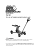
OWNER’S MANUAL TXJ1001 750-LB . OUTBOARD MARINE ENGINE JACK WARNING: Questions, problems, missing parts? Before returning to your retailer, call our customer service department at 1-888-448-6746, 8 a.m.- 5 p.m., PST, Monday-Friday. Read carefully and understand all ASSEMBLY AND OPERATION INSTRUCTIONS before operating. Failure to follow the safety rules and other basic safety precautions may result in serious personal injury.
IMPORTANT Before You Begin Register This Product. For future reference, record the model name, model number, date of manufacture and purchase date of this product. You can find this information on the product. Model Name _________________________ Model Number _________________________ Date of Manufacture _________________________ Date of Purchase _________________________ OWNER / USER RESPONSIBILITY DO NOT OPERATE OR REPAIR THIS PRODUCT WITHOUT READING THIS MANUAL.
INTENDED USE This jack is designed to lift and raise outboard marine engines only. The jack features an overload valve bypass system to prevent jack damage and user injury. Compact design allows use in confined spaces. Easily fits under low mounted marine engines. Meets ASME PALD safety standards. TECHNICAL SPECIFICATIONS Item Description Rated Capacity 750-lbs. Min. Lift Height (in.) 18.89in. Max. Lift Height (in.) 33.1in. Forward Tilt Degree 5° Aft Tilt Degree 12° Left Tilt Degree 9.
IMPORTANT SAFETY CONSIDERATIONS DO NOT OPERATE OR REPAIR THIS EQUIPMENT WITHOUT READING THIS MANUAL. To maintain the Service Jack and user safety, the responsibility of the owner is to read and follow these instructions. Inspect the service jack for proper operation and function. Keep instructions readily available for equipment operators. Make certain all equipment operators are properly trained; understand how to safely and correctly operate the unit.
SAFETY MARKINGS WARNING: 1. 2. 3. 4. 5. 6. 7. 8. 9. 10. 11. 12. 13. 14. Study, understand, and follow all instructions before operating this device. Do not exceed rated capacity. Use only on hard, level surfaces. Lifting device only. Immediately after lifting, support the marine engine with appropriate means. Do not move or dolly the boat while on the jack. Lift only on areas of the marine engine as specified by the marine engine manufacturer. No alterations shall be made to this product.
GENERAL SAFETY INSTRUCTIONS (continued): When you block a load, you secure and support a load that is being lifted. The block(s) or stabilizer(s) should have a weight capacity that is greater than the weight of the load which is being lifted. Center Load on Jack Saddle Center load on jack saddle before lifting engine. Off-center loads and loads lifted when the jack is not level can cause loss of load or damage to the jack. Do not raise or lower the engine unless tools, materials and people are clear.
GENERAL SAFETY INSTRUCTIONS (continued): Additional Notes: Save the receipt, warranty and these instructions. Do not modify the jack in any way. Unauthorized modification may impair the function and/or safety and could affect the life of the equipment. There are specific applications for which the jack was designed. Always check for damaged or worn out parts before using the jack. Broken parts will affect the equipment operation. Replace or repair damaged or worn parts immediately.
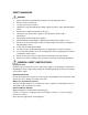
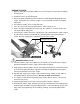
PRODUCT OVERVIEW
SYSTEM AIR PURGE PROCEDURE IMPORTANT: BEFORE FIRST USE Perform the following Air Purge Procedure to remove any air that may have been introduced into the hydraulic system as a result of product shipment and handling. This step is to be completed without any weight on the jack. 1. Turn release valve counter-clockwise one full turn to the open position. 2. Rapidly pump the handle 6-8 times. Leave handle in down position to expose oil fill plug. 3.
RAISING THE JACK 1. Block the boats wheels for lifting stability. Secure the load to prevent inadvertent shifting and movement 2. Position the jack near desired lift point. 3. Refer to the boat manufacturer owner’s manual to locate approved lifting points on the engine. Position the jack so that the saddle is centered and will contact the load lifting point firmly. 4. Assemble the handle, ensure to align with slots. 5. Close the release valve by turning it clockwise until it is firmly closed. 6.
RAISING THE JACK (continued) CAUTION: NEVER WIRE, CLAMP OR OTHERWISE DISABLE THE LIFT CONTROL VALVE TO FUCTION BY ANY MEANS OTHER THAN BY USING THE OPERATOR'S HAND. USE THE HANDLE PROVIDED WITH THIS PRODUCT OR AN AUTHORIZED REPLACEMENT HANDLE TO ENSURE PROPER RELEASE VALVE OPERATION. DO NOT USE EXTENSIONS ON THE OPERATING HANDLE. LOWERING THE JACK 1. Raise load high enough to allow clearance for the jack stands to be removed, then carefully remove jack stands. 2. Remove support stands. 3.
MAINTENANCE INSTRUCTIONS If you use and maintain your equipment properly, it will give you many years of service. Follow the maintenance instructions carefully to keep your equipment in good working condition. Never perform any maintenance on the equipment while it is under a load. Inspection You should inspect the product for damage, wear, broken or missing parts (e.g.: pins) and that all components function before each use. Follow lubrication and storage instructions for optimum product performance.
TO ADD JACK OIL: 1. Position the jack on level ground and lower the saddle. 2. Remove the oil plug. 3. Fill the oil case until oil level is just beneath the lower rim of the oil fill hole. 4. Replace oil plug. 5. Perform the Air Purge Procedure. TO REPLACE JACK OIL: 1. 2. 3. 4. 5. Position the jack on level ground and lower the saddle. Open release valve by turning handle counter-clockwise. Remove the oil fill plug. Turn the jack on its side to drain old oil from the oil fill hole.
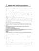
ASSEMBLY DIAGRAM
ASSEMBLY PARTS LIST Item No Description Part Number Qty 1 Handle TXJ1001-001 1 2 Handle Socket TXJ1001-002 1 3 Screw, Handle Socket TXJ1001-003 1 4 Left Bolt, Handle Socket TXJ1001-004 1 5 Spring Washer 18mm TXJ1001-005 2 6 Press Hand Axis Washer TXJ1001-006 2 7 8" Inflatable Rubber Wheels TXJ1001-007 2 8 Support Shaft TXJ1001-008 1 9 Shaft C-Clip 25mm TXJ1001-009 4 10 Cotter Pin M4x40mm TXJ1001-010 1 11 Frame Assembly TXJ1001-011 1 12 Axle, Front Wheel TXJ1
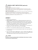
SADDLE ASSEMBLY DIAGRAM
SADDLE ASSEMBLY PARTS LIST Item No Description Part Number Qty 1 Handle TXJ1001-038 1 2 Needle Roller Bearings TXJ1001-039 3 3 Bolt M12X20mm TXJ1001-040 8 4 Right Arm Assembly TXJ1001-041 1 5 Bolt TXJ1001-042 2 6 Square Tube TXJ1001-043 1 7 Spring Column Pin M4X18mm TXJ1001-044 2 8 Locknut M12 TXJ1001-045 2 9 Spring Column Pin M4X30mm TXJ1001-046 1 10 Base Assembly TXJ1001-047 1 11 Len Arm Assembly TXJ1001-048 1 12 Middle Screw Components TXJ1001-049 1 13
TROUBLESHOOTING JACK JACK WILL JACK POOR JACK WILL NOT WILL NOT NOT HOLD WILL NOT LIFTING LIFT TO FULL LIFT LOAD LOAD LOWER CAUSES AND SOLUTIONS EXTENSION Release valve is not completely closed (Turn handle clockwise). Weight Capacity Exceeded. Air is in the hydraulics. Purge air from system. Low oil level. Add oil as required. Oil reservoir is overfilled: Drain excessive oil. Lubricate moving parts.
REPLACEMENT PARTS Consumers for replacement parts and technical questions call us Monday – Friday between 8am and 5:00pm EST at 1-888-448-6746. www.torinjacks.com Please contact our Customer Service Department with any questions you may have concerning parts, use, or maintenance. Not all equipment components are available for replacement, but are illustrated as a convenient reference of location and position in the assembly sequence. Contact Customer Service for equivalent component.