
Use and Care Manual

G005544
1
2
3
4
5
6
7
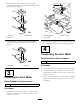
Figure4
1.Hourmeter
5.Singlefemaleterminal,
wiringharness
2.Femaleboxconnector6.Enclosedmaleterminal,
wiringharness
3.Positivemaleplug7.Negativemaleplug,hour
meter
4.Ringconnectortonegative
batteryterminal,wiring
harness
8.Negativeconnector(black)
4.Locatethesinglefemaleandtheenclosedmale
terminalsattheoppositeendofthewiringharness
(Figure4).
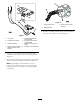
5.Routetheseterminalstotheundersideofthecontrol
panelandlocatetheignitionswitchbase(Figure5).
Note:Dependingonthemachine,itmaybe
necessarytoremovethefourscrewssecuringthe
controlpaneltotheconsoletoaccesstheignition
switchbase.
G005545
1
2
3
Figure5
1.Ignitionswitchbase
3.Singlewireandouter
terminal
2.Wiringharness
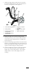
6.Removethesinglewirefromtheouterterminalat
thebaseoftheignitionswitch(Figure5).
3