
Service Manual

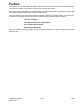
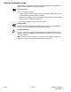

Table Of Contents
- Revision History
- Preface
- Chapter 1 : Safety
- Chapter 2 : Specifications and Maintenance
- Chapter 3 : Troubleshooting
- Chapter 4 : Power Head Assembly
- Chapter 5 : Controls
- Chapter 6 : Charger and Battery
- Chapter 7 : Shrouds
- Chapter 8 : Motor Driver
- Chapter 9 : Battery Terminal
- Chapter 10 : Motor
- Appendix A: Foldout Drawings
- Electrical Schematic
- Electrical Schematic

ServiceProcedureIcons
ThefollowingiconsappearthroughoutthisServiceManualtobringattentionto
specicimportantdetailsofaserviceprocedure.
CriticalProcess
Thisiconisusedtohighlight:
•Installingsafetyequipment(shields,guards,seatbelts,brakes,andR.O.P .S.
components)thatmayhavebeenremoved
•Dimensionsorsettingsthatmustbemaintainedforpropermachineoperation
•Aspecicfastenertighteningsequence
•Componentorientationthatmaynotbeobvious
CriticalTorque
Thisiconisusedtohighlightanassemblytorquerequirementthatisdifferent
thanwhatisrecommendedintheStandardTorqueT ables.
FluidSpecications
Thisiconisusedtohighlightuidspecicationsandcapacitiesthatareless
common,andmaynotappearonthemachineservicedecalorinthemachine
Operator’sManual.
Note:RefertotheservicedecalonthemachineandthemachineOperator’s
Manualforcommonlyuseduidspecicationsandcapacities.
Preface
Page4
60vWPMServiceManual
3429-828RevA