FORM NO. 3321–135 ProLine Pruner Model No. 53035 — 8900001 & Up 16” & 18” Gas Modèle No. 51903 — 790000001 et suivants Modèle No. 51904 — 790000001 et suivants Modèle No. 51906 — 790000001 et suivants Modèle No. 51907 — 790000001 et suivants 16” & 18” Gas Modelos N. 51903 — 790000001 y siguientes Modelos N. 51904 — 790000001 y siguientes Modelos N. 51906 — 790000001 y siguientes Modelos N.
WARNING: The engine exhaust from this product contains chemicals known to the State of California to cause cancer, birth defects, or other reproductive harm.
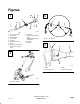
Figures 1 3 1. 2. 3. 4. 5. 6. 7. 8. 9. Gearcase 10. Throttle Trigger and Stop Switch 11. Throttle Cable and Stop Switch Wires 12. Fuel Tank 13. Air Filter Chain and Guide Bar Pruner Head Shaft Assembly Loop Handle Shaft Grip Clutch Drum Housing Engine Model and Serial Number Decal (on rear of engine stand) 1. 50 ft. (15 m) Minimum 4 2 1. Engine 2. M5 x 20 Screw (4) 3. Shaft 4. Clutch Drum Housing 1.
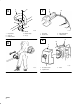
5 7 1. Loop Handle 2. Screw (4) 3. Rubber Sleeve m-2970 m-2972 1. Shaft Grip 2. Plastic Tube 4. Bottom Clamp 5. Nut (4) 3. Stop Switch Wires 4. Throttle Cable 8 6 m-3041 m-2971 ii 1. Air Cleaner Cover 2. Cylinder Cover 3.
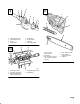
9 11 m-2973 1. 2. 3. 4. 5. 6. 7. 8. Throttle Cable Housing Cable Adjuster Sleeve Locknut Throttle Cable 10 Slotted Fitting Recessed Hole Cable Lug Carburetor Bracket m-3037 1. Chain Tensioner Adjustment Pin 2. Bar Stud (2) 3. Bar Stud Spacer (required with 11-inch bar; provided with unit) 4. Chain Tensioner Screw 5. Chain Tensioner Adjustment Pin Hole 6. Guide Bar 1. Cable Adjuster Sleeve 2. Carburetor Throttle Cam 3.
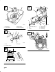
12 14 m-3039 1. Oil Tank Filler Cap 2. Oil Discharge Adjustment Screw 15 1. Rim Sprocket 2. Chain m-3038 3. Guide Bar 13 m-2978 1. Primer Bulb 16 1. Sprocket Cover 2. Chain Travel Direction 3. Bar Stud Nuts 2. Fuel Return Line m-3032 4. No Clearance or Slack between Chain and Bottom of Guide Bar m-2938 1. Starter Handle iv 2.
17 19 m-2939 1. Stop Switch 2. Fast-idle Lock 3. Throttle Trigger (in fast-idle start position) 4. Throttle Trigger (in idle position) 1. 2. 3. 4. m-3030 Hearing Protection Eye Protection Right Arm Slightly Bent Left Arm Fully Extended, Hand Holding Loop Handle 18 20 5. Hand Holding Throttle Grip, Fingers on Throttle Trigger m-2974 1. Idle Speed Adjustment Screw m-2997 1. Air Filter Cover 2. Filter Screen 3.
21 24 m-3010 1. Filter Screen 2. Cutout (typical) 3. Air Filter Cover 4. Plastic Post (typical) 22 1. Wire 2. Fuel Pick-up Hose 25 3. Fuel Filter m-3002 ÎÎÎÎÎ ÎÎÎÎÎ ÎÎÎÎÎ ÎÎÎÎÎ ÎÎÎÎÎ ÎÎÎÎÎ m-2932 1. .024”–.028” (0.6–0.7 mm) vi 4. Spark Arrester 5. Muffler Cover 6. Muffler Body m-2931 23 1. Socket Head Screw (5) 2. Tail 3.
Contents Introduction . . . . . . . . . . . . . . . . . . . . . . . . . . . . Safety . . . . . . . . . . . . . . . . . . . . . . . . . . . . . . . . . Operator Safety . . . . . . . . . . . . . . . . . . . . . Pruner Safety . . . . . . . . . . . . . . . . . . . . . . . Fuel Safety . . . . . . . . . . . . . . . . . . . . . . . . . Pruner Operating Safety . . . . . . . . . . . . . . . Safety and Instruction Decals . . . . . . . . . . Assembly . . . . . . . . . . . . . . . . . . . . . . . . . . . . . .
DANGER signals an extreme hazard that will cause serious injury or death if the recommended precautions are not followed. WARNING signals a hazard that may cause serious injury or death if the recommended precautions are not followed. CAUTION signals a hazard that may cause minor or moderate injury if the recommended precautions are not followed. Two other words are also used to highlight information.
7. 8. Shut off the engine and be certain the cutting chain has completely stopped rotating before inverting the Pruner, performing maintenance on or working on the machine. If running problems or excessive vibration occur, stop immediately and inspect the unit for the cause. If the cause cannot be determined or is beyond your ability to correct, return the Pruner to your servicing dealer for repair. Fuel Safety 1. Gasoline is highly flammable and must be handled and stored carefully.
Safety and Instruction Decals Safety decals and instructions are easily visible to the operator and are located near any area of potential danger. Replace any decal that is damaged or lost. ON SHAFT (Part No. M221501) ON SHAFT (Part No. M221529) ON SHAFT (Part No. M219937) 4 ON ENGINE (Part No.
Assembly Assembling Engine and Drive Shaft Assembly The drive shaft, clutch drum housing and gearcase are assembled. Attach the clutch drum housing to the engine using the four M6 x 20 screws supplied with the unit (Fig. 4). 3. Connecting Throttle Cable 1. With the air cleaner cover removed, insert the throttle cable through the cable adjuster sleeve on the carburetor bracket. Make sure the end of the cable housing is seated positively in the sleeve (Figs. 9 and 10). 2.
Before Operation • Always wear gloves when handling the Chain Oil Pruner chain. 3. Place the chain over the rim sprocket and into the groove on the guide bar. Make sure the cutting teeth edges are facing forward on the top side of the guide bar (Fig. 12). 4. Pull the guide bar forward until the chain tensioner adjustment pin hole is positioned over the chain tensioner adjustment pin. If necessary, turn the chain tensioner screw in the appropriate direction to align the pin with the hole.
Oil and Fuel POTENTIAL HAZARD • Gasoline contains gasses that can build up pressure inside a gas tank. WHAT CAN HAPPEN • Fuel can be sprayed on you when removing gas cap. POTENTIAL HAZARD • In certain conditions gasoline is extremely flammable and highly explosive. HOW TO AVOID THE HAZARD • Remove fuel cap slowly to avoid injury WHAT CAN HAPPEN from fuel spray. • A fire or explosion from gasoline can burn you, others, and cause property damage. 4.
Recommended Fuel Type Use clean, fresh lead-free gasoline, including oxygenated or reformulated gasoline, with an octane rating of 85 or higher. To ensure freshness, purchase only the quantity of gasoline that can be used in 30 days. Use of lead-free gasoline results in fewer combustion chamber deposits and longer spark plug life. Use of premium grade fuel is not necessary or recommended.
Mixing Instructions 4. Keep all bystanders, children and animals away from the working area. IMPORTANT: Never mix gasoline and oil directly in the Pruner fuel tank. 1. Always mix fuel and oil in a clean container approved for gasoline. 2. Mark the container to identify it as fuel mix for the Pruner. 3. Use regular unleaded gasoline and fill the container with half the required amount of gasoline. 4. Pour the correct amount of oil into the container then add the remaining amount of gasoline. 5.
2. Move the choke lever to the open ( ) position and move the stop switch to the “ON” position (Figs. 16 and 17). 3. Leave the throttle trigger in the idle position and pull the starter handle (Figs. 16 and 17). 4. The Pruner chain may be rotating during idle speed adjustment. Wear the recommended personal protective equipment and observe all safety instructions. Keep hands and body away from the Pruner chain.
Before using the Pruner, check the following: 1. • Make certain all moving parts have stopped and disconnect the spark plug before inspecting the equipment for damage. • Never use a Pruner that has a damaged chain or guide bar. Make sure the chain oil tank on the pruner head is full (Fig. 14). IMPORTANT: When filling an empty oil tank, wait approximately 60–90 seconds before starting the Pruner. This will give the oil time to flow from the tank to the pump.
Adjusting the Chain Oil Discharge Rate 5. IMPORTANT: The air filter screen is designed to fit into the air filter cover ONE WAY ONLY. Make sure the cutouts in the screen fit onto the matching plastic posts in the air filter cover. The fit should be snug (Fig. 21). To check the chain oil discharge rate: 1. Position the nose of the guide bar about eight inches (20 cm) from a smooth surface. 2. Run the engine wide open for 30–60 seconds. You should see a light oil spray on the surface. 6.
Spark Plug Maintenance Interval • The spark plug should be removed from the engine and checked after each 25 hours of operation. • Replace the spark plug after every 100 hours of operation. Air must flow freely around and through the cylinder cooling fins to prevent engine overheating. Leaves, grass, dirt and debris buildup on the fins will increase the operating temperature of the engine, which can reduce engine performance and shorten engine life. Cooling Fin Cleaning 1.
Spark Arrester Maintenance 1. 2. 5. With the engine at ambient (room) temperature, loosen the knob and remove the air cleaner cover (Fig. 8). Loosen the knob and lift off the cylinder cover (Fig. 8). Clean the muffler body and cover with a safety solvent and a stiff brush (Fig. 24). IMPORTANT: Be careful not to allow any dirt or debris to fall into the exhaust ports, as this can cause engine damage. 6. To reassemble the muffler cover to the muffler: A.
The Toro Pruner will provide maximum performance for many, many hours if it is maintained properly. Good maintenance includes regular checking of all fasteners for correct tightness, and cleaning the entire machine. 5. POTENTIAL HAZARD • Oil may squirt out of the spark plug opening when you pull the starter handle. Storage WHAT CAN HAPPEN • Oil can cause eye injuries. For long-term storage of the Pruner (Fig. 25): 1. Empty the fuel tank into a suitable fuel storage container. 2.
Specifications Engine Displacement 26cc Bar Length 10” Bar 3/8” Pitch Shaft Straight (59”) steel drive shaft with 6 ball bearings, 5 bushings Weight 15.5 lbs. (7 kg) Oiler Auto (continuous) Dual Isolation – grip and engine mount Spark Plug NGK BPM6Y Spark Plug Gap .024–.028 in (0.6–0.7mm) Anti Vibration Carburetor Walbro – Choke Type Ignition System Solid State Tool Kit yes Fuel Tank Capacity 0.85 qts. (0.
Federal and California Emission Control Warranty Statement A Two Year Limited Warranty Your Warranty Rights and Obligations The U.S. Environmental Protection Agency (EPA), the California Air Resources Board (CARB) and Toro are pleased to explain the emission control system warranty on your 1995 and later utility/lawn/garden equipment engine. In California, new utility/lawn/garden equipment engines must be designed, built and equipped to meet the State’s stringent anti–smog standards.
Failures caused by abuse, neglect, or improper maintenance are not covered. The use of add–on or modified parts can be grounds for disallowing a warranty claim. The manufacturer is not liable to cover failures of warranted parts caused by the use of add–on or modified parts. Toro is liable for damages to other engine components caused by the failure of a warranted part still under warranty.
warranty validation. The owner shall not be charged for diagnostic labor which leads to the determination that a warranted part is defective, if the diagnostic work is performed at a warranty station. The Toro Company is not liable for indirect, incidental or consequential damages in connection with the use of the TORO Products covered by this warranty, except for damages to other engine components caused by the failure of a warranted part still under warranty.
THE TORO TOTAL COVERAGE GUARANTEE A OneĆYear Limited Warranty (A TwoĆYear Full Warranty for Residential Use) LCG What Is Covered By This Express Warranty? The Toro Company promises to repair any TORO Product used for commercial, institutional, or rental purposes if defective in materials or workmanship for a period of one year from the date of purchase. The cost of parts and labor are included, but the customer pays the transportation cost.