Form No. 3447-108 Rev A Front Tine Tiller/Cultivator Model No. 58604—Serial No. 321000001 and Up Register at www.Toro.com.
It is a violation of California Public Resource Code Section 4442 or 4443 to use or operate the engine on any forest-covered, brush-covered, or grass-covered land unless the engine is equipped with a spark arrester, as defined in Section 4442, maintained in effective working order or the engine is constructed, equipped, and maintained for the prevention of fire.
Contents Safety Safety ....................................................................... 3 General Safety ................................................... 3 Safety and Instructional Decals .......................... 4 Setup ........................................................................ 6 1 Installing the Tines and Shields ........................ 7 2 Installing the Handlebars ................................. 8 3 Installing the Drag Stake ..................................
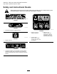
instruction. Failure to comply with these instructions may result in personal injury or death. Safety and Instructional Decals Safety decals and instructions are easily visible to the operator and are located near any area of potential danger. Replace any decal that is damaged or missing. decal133-8062 133-8062 decal144-4848 144-4848 1. Squeeze the throttle to engage the tines. decal144-4873 144-4873 1. Warning—read the Operator’s Manual. 2.
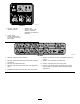
decal144-4874 144-4874 1. Warning—read the Operator’s Manual. 3. Installing the shields—slide the side shield on, raise the handlebars, and install the hand knob. 2. Thrown object hazard—keep shields in place when outer tines are installed. decal148-4868 148-4868 6. Warning—look behind you when operating the machine in reverse. 7. Warning—do not operate over buried lines. 1. Warning—read the Operator’s Manual. 2. Warning—all operators should be trained before operating the machine. 3.
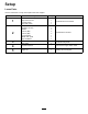
Setup Loose Parts Use the chart below to verify that all parts have been shipped. Procedure 1 2 3 4 5 Description Qty. Use Left outer tine set Right outer tine set Left side shield Right side shield Bolt (M8 x 40 mm) Bolt (M6 x 40 mm) Washer Locknut (M8) Locknut (M6) Left handlebar Middle dash panel Right handlebar Lock pin Drag stake 1 1 1 1 4 4 4 4 4 1 1 1 1 1 No parts required – Connect the engine switch cable. Engine oil 1 Adding oil to the engine. 6 Install the tines and shields.
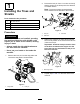
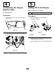
2. 1 Remove the lock pin from 1 inner tine and verify that the arrows on the tines point in the direction of forward rotation. Note: The arrows rotate counterclockwise Installing the Tines and Shields when viewed from the left side of the machine. Parts needed for this procedure: 1 Left outer tine set 1 Right outer tine set 1 Left side shield 1 Right side shield g358136 Figure 4 Procedure 1. Lock pin 2.
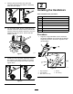
5. Remove the hand knobs from the lower handlebar assembly and rotate the assembly away from the engine. 2 Installing the Handlebars Parts needed for this procedure: g358170 Figure 6 6. For each side shield, align the shield grooves with the center tine shield, slide the side shield onto the center tine shield, and push it until you hear/feel it click into place. Ensure that the shield is secure.
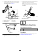
2. Install the middle dash panel. Route the engine switch cable through the hole on the left side of the panel as shown in Figure 11. 5. Insert the Z-bend end of the drive cable into the middle hole of the drive-control lever. Note: Ensure that there is no excess slack in the cable and that the lever remains in the full up position. g358470 Figure 12 1. Drive-control lever holes g358244 Figure 10 1. Bolt—M6 x 40 mm (4) 3. Drive cable 2. Middle dash panel 4.
4 5 Connecting the Engine Switch Cable Adding Oil to the Engine Parts needed for this procedure: 1 No Parts Required Procedure 1. Engine oil Procedure Plug the engine switch cable into the engine on/off switch. 1. Move the machine to a level surface. 2. Remove the dipstick. g361563 Figure 13 g360549 Figure 15 2. Plug the other end of the cable into the connector on the engine. g361571 Figure 14 10 1. Filler tube 3. Upper limit 2. Dipstick 4. Lower limit 3.
Throttle Control Product Overview The throttle controls the engine speed, and it has a continuous-variable setting. Operate the machine using full throttle for best performance. Choke Lever Move the choke lever on the engine to the CHOKE position when initially starting a cold engine, then move it into the RUN position once started. Drive-Control Lever Squeeze the drive-control lever to the hand grip to engage the tines. Release it to disengage the tines.
Operation • Do not fill the fuel tank indoors. • Do not overfill the fuel tank. Replace the fuel cap and tighten it securely after fueling. Clean up spilled fuel before starting the engine. Note: Determine the left and right sides of the machine from the normal operating position. • Do not fill containers inside a vehicle or on a truck or trailer bed with a plastic liner. Always place containers on the ground, away from the vehicle before filling.
Adding Fuel Changing the Tine Configuration Fuel Specifications WARNING Type Unleaded gasoline Minimum octane rating 87 (US) or 91 (research octane; outside the US) Ethanol No more than 10% by volume Methanol None MTBE (methyl tertiary butyl ether) Less than 15% by volume Oil Do not add to the fuel When the outer tines are installed, operating the machine without the side shields could expose you or others to tine contact, causing injury or death.
• Narrow tilling—41 cm (16 inch) width 4. For narrow and wide tilling configurations, continue as follows: A. Install the lock pins. Important: Install the lock pin from the front of the tiller so that the wire hinges over the top of the tine pipe and latches to the pin on the rear of the tine. The tines could inadvertently detach during tilling if the lock pins are installed incorrectly.
Adjusting the Handlebars Performing Daily Maintenance You can adjust the handlebar height 2 ways. • Remove the fasteners from the left and right Before starting the machine each day, perform the Each Use/Daily procedures listed in Maintenance (page 18). handlebars, align the holes at the desired height, and secure the handlebars. During Operation During Operation Safety General Safety • Use your full attention while operating the machine.
Starting the Machine for all moving parts to stop, and disconnect the wire from the spark plug before examining the machine for damage. Vibration is often a warning sign of trouble. Make all necessary repairs before resuming operation. 1. Move the engine on/off switch to the ON position. 2. Move the choke lever to the CHOKE position. Note: A warm or hot engine may not require • Do not operate the machine at high transport choking. speeds on hard or slippery surfaces.
Adjusting the Drag Stake After Operation The drag stake helps regulate tilling depth and prevents the tiller from jerking forward during operation. Set the drag stake in the lowest position to increase resistance to forward motion and to dig deeper; raise the drag stake for transport. 1. Move the machine to a level surface, shut off the engine, and wait for all moving parts to stop. 2. Remove the lock pin.
Maintenance • Never tamper with safety devices. Check their Maintenance Safety • To ensure optimum performance of the machine, proper operation regularly. use only genuine Toro replacement parts and accessories. Replacement parts and accessories made by other manufacturers could be dangerous, and such use could void the product warranty.
Pre-Maintenance Procedures Engine Maintenance Preparing for Maintenance Service Interval: Every 25 hours 1. 2. Servicing the Air Cleaner Move the machine to a level surface, shut off the engine, and wait for all moving parts to stop. 1. Refer to Preparing for Maintenance (page 19). 2. Remove the air-cleaner cover. Disconnect the spark-plug wire from the spark plug. g357771 Figure 27 g360561 1. Spark-plug wire 3. Figure 28 1. Air-cleaner cover 2.
Servicing the Engine Oil Changing the Engine Oil Engine-Oil Specifications Service Interval: After the first 20 hours/After the first month (whichever comes first)—Change the engine oil. Engine oil capacity 0.35 L (11.8 fl oz) Oil viscosity Refer to the chart below. API service classification SJ or higher Every 25 hours—Change the engine oil when operating in high temperatures or under heavy loads. Every 50 hours—Change the engine oil.
Servicing the Spark Plug Checking the Spark Plug Service Interval: Every 50 hours Important: Do not clean the spark plug(s). Ensure that the air gap between the center and side electrodes is correct before installing the spark plug. Always replace the spark plug(s) when it has a black coating, worn electrodes, an oily film, or cracks. Use a spark plug wrench for removing and installing the spark plug(s) and a gapping tool/feeler gauge to check and adjust the air gap.
Fuel System Maintenance 6. Remove the filter by using a socket to turn it counterclockwise. DANGER In certain conditions, fuel is extremely flammable and highly explosive. A fire or explosion from fuel can burn you and others and can damage property. Refer to Fuel Safety (page 12) for a complete list of fuel related precautions. g360644 Servicing the Fuel Filter Figure 35 1. Refer to Preparing for Maintenance (page 19). 2. Drain fuel from the fuel tank. 3.
Belt Maintenance difference should be 0.32 to 0.6 cm (1/8 to 1/4 inch). 4. Checking and Adjusting the Belt Tension Service Interval: Every 10 hours If the belt needs adjustment, hold the lower jam nut in place and adjust the upper jam nut in 0.32 cm (1/8 inch) increments. Check the tension again, and repeat as necessary. Note: If the tension is incorrect and you cannot The belt tension may decrease over time. You may need to adjust the belt within the first half hour of operation.
Replacing the Drive Belt Installing the Belt 1. Service Interval: Every 50 hours Place belt in the transmission pulley groove. Removing the Belt 1. Remove the pulley cover. g358509 Figure 42 1. Engine pulley 3. Transmission pulley 2. Belt 2. Gently pull the engine recoil rope to rotate the engine pulley while forcing the belt into the groove. 3. Check the belt tension; adjust it as necessary. 4. Install the pulley cover. g358486 Figure 40 1. Bolt—M6 x 35 mm (4) 2. Pulley cover 2.
Cleaning Storage Cleaning the Tine Axle Shaft Storage Safety • Shut off the machine and wait for all moving parts to stop before you leave the operator’s position. Disconnect the spark-plug wire, keep it away from the plug to prevent accidental starting, and allow the machine to cool before adjusting, fueling, unclogging, servicing, cleaning, or storing the machine. Run the engine dry or remove the fuel with a hand pump; never siphon the fuel. If you must drain the fuel tank, do it outdoors.
D. Start the engine and run it until it shuts off. E. Dispose of fuel properly. Recycle the fuel according to local codes. Important: Do not store fuel containing stabilizer/conditioner longer than the duration recommended by the fuel-stabilizer manufacturer. 7. Remove and check the condition of the spark plug; refer to Servicing the Spark Plug (page 21). With the spark plug removed from the engine, pour 15 ml (1 tablespoon) of engine oil into the spark plug hole.
Troubleshooting Problem The engine does not start. Possible Cause Corrective Action 1. The fuel tank is empty. 1. Add fuel. 2. The spark-plug wire is loose or disconnected. 3. The engine switch is in the OFF position. 4. The choke lever is not in the CHOKE position during cold start. 2. Install the wire on the spark plug. The engine runs rough or floods during operation. 1. The air filter is dirty. 1. Clean or replace the air filter. The engine is difficult to start. 1.
California Proposition 65 Warning Information What is this warning? You may see a product for sale that has a warning label like the following: WARNING: Cancer and Reproductive Harm—www.p65Warnings.ca.gov. What is Prop 65? Prop 65 applies to any company operating in California, selling products in California, or manufacturing products that may be sold in or brought into California.