TOSHIBA UNINTERRUPTIBLE POWER SYSTEM THREE-PHASE 80 kVA UPS 4200FA User’s Manual Document Number: 56418-004 Date: November 2007
TOSHIBA 4200FA User’s Manual
TOSHIBA 4200FA THREE-PHASE 80 kVA UNINTERRUPTIBLE POWER SYSTEM USER’S MANUAL FOR MODELS T42F3F800FAXXN T42F3#800FAXXN T42#3F800FAXXN TOSHIBA INTERNATIONAL CORPORATION INDUSTRIAL DIVISION 13131 West Little York Road Houston, TX 77041-9990 4200FA User’s Manual
TOSHIBA 4200FA User’s Manual
TOSHIBA IMPORTANT NOTICE The Instructions contained in this manual are not intended to cover all of the details or variations in equipment or to provide for every possible contingency to be met in connection with installation, operation, or maintenance. Should further information be required or should particular problems arise which are not covered sufficiently the matter should be referred to the local TOSHIBA sales office.
TOSHIBA Purpose and Scope of Manual This manual provides information on how to safely install, operate, and maintain your TOSHIBA power electronics product. This manual includes a section on General Safety Instructions that describes the warning labels and symbols that are used throughout the manual. Read the manual completely before installing, operating, or performing maintenance on this equipment.
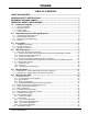
TOSHIBA TABLE OF CONTENTS TABLE OF CONTENTS..................................................................................................... i GENERAL SAFETY INSTRUCTIONS.............................................................................. 1 EQUIPMENT WARNING LABELS ................................................................................... 2 IMPORTANT SAFETY INSTRUCTIONS .......................................................................... 5 1.0 Product Description................
TOSHIBA 6.11 .. Start-up Procedure ......................................................................................................................... 39 6.12 .. Shutdown Procedure ...................................................................................................................... 40 6.13 .. Keypad Overview............................................................................................................................ 41 6.14 .. Key Functions ..............................
TOSHIBA GENERAL SAFETY INSTRUCTIONS DO NOT attempt to install, operate, maintain or dispose of this equipment until you have read and understood all of the product safety information and directions that are contained in this manual. Safety Alert Symbol The Safety Alert Symbol indicates that a potential personal injury hazard exists. The symbol is comprised of an equilateral triangle enclosing an exclamation mark.
TOSHIBA EQUIPMENT WARNING LABELS DO NOT attempt to install, operate, maintain or dispose of this equipment until you have read and understood all of the product warnings and user directions that are contained in this instruction manual. Shown below are examples of warning labels that may be found attached to the equipment. DO NOT remove or cover any of the labels. If the labels are damaged or if additional labels are required, contact your TOSHIBA representative for additional labels.
TOSHIBA DANGER HAZARDOUS VOLTAGES Hazardous voltages are used in the operation of this equipment and could cause severe personal injury or loss of life. The following precautions should be observed to reduce the risk of injury or death. Only qualified technicians familiar with this equipment and the information supplied with it should be permitted to install and operate this equipment.
TOSHIBA DANGER RISK OF ELECTRIC SHOCK Capacitors stay charged after power has been shut off. Accidental contact with live parts can cause personal injury and death. Turn off and lock out all power sources. Wait at least five (5) minutes for power to dissipate then check voltage before servicing.
TOSHIBA IMPORTANT SAFETY INSTRUCTIONS This manual contains important instructions that should be followed during the installation, operation, and maintenance of the UPS and its batteries. Turn off, lockout, and tagout all power sources before proceeding to connect the power wiring to the equipment or when performing maintenance. Hardwire type UPS units are not equipped with an over-current protection device nor an output disconnect for the AC output.
TOSHIBA This unit contains sealed lead acid batteries. Lack of preventative maintenance could result in batteries exploding and emitting gasses and/or flame. An authorized technician must perform annual preventative maintenance. CAUTION Failure to replace a battery before it becomes exhausted may cause the case to crack; possibly releasing electrolyte from the battery resulting in secondary faults such as odor, smoke, and fire.
TOSHIBA INSTRUCTIONS IMPORTANTES CONCERNANT LA SÉCURITÉ ATTENTION Cette notice contient des instructions importantes concernant la sécurté Un batterie puet présenter un risque de choc électrique, de brûlure par transfert d’ énergie. ATTENTION L’élimination des batteries est règlementèe.
TOSHIBA 1.0 Product Description 1.1 Theory of Operation An Uninterruptible Power System (UPS) is a system that is installed between the commercial power and the load equipment. The UPS provides steady AC output power during commercial power fluctuations and interruptions. During normal operation the UPS receives commercial AC power and removes any high voltage spikes and transients caused by switching or faults on the main utility.
TOSHIBA 2.0 Unpacking/Inspection/Storage/Disposal 2.1 Unpacking the UPS Equipment 1) Upon receipt of the UPS, a careful inspection for shipping damage should be made. 2) For international units, remove the screws that attach the shipping crate panels to each other and to the pallet. Remove the crate and foam packing material. 3) Unbolt the unit from the shipping pallet. 4) Lift the UPS from the pallet using a forklift that has sufficient capacity. Approach the UPS only from the front or rear.
TOSHIBA 2.2 UPS Equipment Inspection UPS Equipment Inspection Upon receipt of the UPS, a careful inspection for shipping damage should be made. Use caution when removing unit from pallet. Refer to labels or documentation attached to packing material. After Unpacking 1) Check the unit for loose, broken, bent or other damaged parts. If damage has occurred during shipment, keep all packing materials for return to the shipping agent.
TOSHIBA 3.0 Precautions Because of the external dimensions of the 4200FA UPS and the way the outer panels are to be removed; only a minimum amount of space around the unit is required for ventilation and maintenance access. Figure 3.1 shows the minimum clearances required for proper UPS installation. 4200 FA User’s Manual RIGHT 0” (0mm) Installation Precautions 1) Install the UPS in a stable, level, and upright position that is free of vibration.
TOSHIBA 11) After ensuring that all power sources are turned off and isolated in accordance with established lockout/tagout procedures, connect power source wiring of the correct voltage to the input terminals of the UPS. Connect the output terminals of the UPS to an applicable load type application (refer to NEC Article 300 – Wiring Methods and Article 310 – Conductors For General Wiring). Size the branch circuit conductors in accordance with NEC table 310.16.
TOSHIBA CAUTION Do not EPO (Emergency Power OFF) the UPS and then reset the breaker until the UPS has been fully discharged. The UPS could be damaged if the unit is not fully powered down before the breaker is reset. 4.0 UPS Connections 4.1 UPS Power and Control Connections The following illustration shows the wiring connections to the input and output termination points and the Control Circuit Terminal Blocks for the 4200FA 80 kVA UPS.
TOSHIBA 4.1.1 Recommended Wire Size and Tightening Torque for UPS Input/Output Terminals Minimum/Maximum Wire Size and Tightening Torque of UPS Input and Output Terminals Main Input & Bypass Input AWG (H1 – H3, BYP1, BYP2, BYP3) AWG (N, BYPN) Tightening Torque (in-lbs.
TOSHIBA 4.1.2 Power Connection Cable Routing 1) Use separate metal conduits for routing the input power, output power, battery, and control circuits. 2) A separate ground cable should be run inside of the conduit with the input power, output power, and control circuits. 3) Always ground the unit to prevent electrical shock and to help reduce electrical noise. 4) Follow wire size and tightening torque recommendations provided in this manual.
TOSHIBA Dual Input UPS with input transformer. Shown with bottom cable entry configuration.
TOSHIBA Single Input UPS with no transformers. Shown with bottom cable entry configuration.
TOSHIBA Dual Input UPS with no transformers. Shown with bottom cable entry configuration.
TOSHIBA Single Input UPS with input transformer. Shown with top cable entry configuration.
TOSHIBA Dual Input UPS with input transformer. Shown with top cable entry configuration.
TOSHIBA Single Input UPS with no transformers. Shown with top cable entry configuration.
TOSHIBA Dual Input UPS with no transformers. Shown with top cable entry configuration.
TOSHIBA 4.1.3 Dual Input Configuration Units are shipped from the factory wired for single input configuration. For those requiring a dual input configuration see below. This change should only be performed by factory trained service personnel and not by the end user. Bypass jumpers are factory installed on bypass bus bars. Single Input Configuration Move wires from bypass bus bars to stand offs to configure for dual input.
TOSHIBA 4.2 Control Circuit and External Battery Interface Connections The following illustrates the wiring connections of the Control Circuits and Battery Interface Circuits. 4.1.4 Recommended Wire Size and Tightening Torque UPS Control and Battery Interface Minimum Wire Size and Tightening Torque for UPS Control and Battery Interface Circuits USE MINIMUM 75° C COPPER WIRING TERMINAL (TERMINAL #) AWG TIGHTENING TORQUE *UPS CONTROL CIRCUITS (1-18) 14-16 8 in-lbs.
TOSHIBA 4.2 Communication Interface 4.2.1 Remote Contact The remote contact interface is a standard feature and is available as dry switch contacts through a DB9 male connector located under the Remote Eye Cover on the front of the UPS (see Section 4 for location). The following schematic shows the contact state and pin assignment for each signal and the associated DB9 connector pin-out.
TOSHIBA 4.2.2 RS-232C The RS-232C serial communication interface is available via a DB9 female connector located under the Remote Eye Cover on the front of the UPS (see Section 4 for location). This interface allows control of the UPS from a personal computer running special TOSHIBA software. The computer and the UPS are connected through a serial RS-232C communication port. The available data from the UPS, via the RS-232C communication link is shown below.
TOSHIBA 5.0 Specifications 5.1 Specifications – 4200FA 80kVA without Internal Transformer Model Number Rated Output Capacity External Dimen.
TOSHIBA 5.
TOSHIBA 6.0 Operating the UPS 6.1 Operating the UPS 6.1.1 AC Input Mode (normal operation) The following illustration shows circuit power flow when the UPS is operating normally in the AC input mode. The converter of the UPS, including a boost chopper circuit, converts the AC input power to DC power. The boost chopper circuit maintains a constant voltage and provides current limiting for battery charging. It also supplies a DC voltage of the proper level to the inverter section.
TOSHIBA 6.1.3 Battery Backup Mode The following illustration shows power flow during the battery backup mode. In the event of an AC power failure the batteries of the UPS instantly begin supplying DC power to the UPS to the main inverter circuit. This circuit converts the DC power into AC power. The AC power is available at the output of the unit. This back-up process will continue until the UPS battery voltage drops below a specific minimum level.
TOSHIBA 6.2 Battery Backup Time and Discharge Process The UPS system, when used in conjunction with a TOSHIBA designed Battery System, is designed to provide several minutes of back-up time for the 4200FA UPS (Refer to the Battery System Manual for back-up times). These times are valid for full-load operation. At half-load operation the batteries can provide approximately 2 times the specified value.
TOSHIBA 6.4 Battery Recharging The illustration below shows the battery recharge process after a full discharge. The recharge process typically consists of three periods. During the first period, the charging current is maintained at approximately 20.0 amperes. This current is the maximum value that can be used to charge the batteries (for minimal recharge time) while assuring safety and long battery life.
TOSHIBA 6.5 Front Panel Layout (All Units) 4-line liquid crystal display screen (see Section 6.9) Emergency Power Off switch (see Section 6.6) Line-1 Line-2 Line-3 Line-4 MONI BATT F1 RUN/STOP key switch UPS EPO STOP RUN INPUT OUTPUT BATT TEST BUZZ STOP AC IN INV BYP BATT RESET Green light-emitting diodes (LED) (see Section 6.8) 4200 FA User’s Manual MENU ENTER FAULT Red light-emitting diode (LED) (see Section 6.
TOSHIBA 6.6 EPO (Emergency Power Off) Function The 4200FA UPS system is equipped with terminals for receiving an emergency power-off (EPO) closed contact switch command from two locations: (1) a remote location (see Section 4.2 Terminal Block Details) and (2) from a front panel mounted EPO switch (see Section 6.5 Front Panel Layout). This safety feature enables quick shutdown of the UPS AC output and battery circuits.
TOSHIBA 6.8 User Notification LEDs The following is a list of the user-notification LEDs and their function. On when the UPS has normal AC input power that is within tolerance. If there is an input power failure this LED is off. If there is no power failure and the input voltage is in an overvoltage condition, the AC IN LED will flicker on and off rapidly (0.4 sec on and 0.4 sec off). If there is no power failure and the input voltage is in an under-voltage condition the AC IN LED will be off.
TOSHIBA 6.9 LCD Functions The LCD display is a 4-line by 20-character display. The LCD display conveys system operational information. It should be used in conjunction with the LED display (see Section 6.8) and the audible alarms (see Section 6.7) for total system monitoring. Listed below are the types of user-notification messages that are available for each line of the LCD display screen and a description of each. This message displayed is determined by the UPS operating mode and conditions.
TOSHIBA 6.9.4 Line-4 System Messages Line-4 messages reflect the UPS operating conditions. Warning messages will be displayed when an abnormal operating condition occurs. The following table shows the allowable Line-4 messages.
TOSHIBA 6.10 Initial Battery Charge The battery of the UPS must be charged before it is used for the first time or if the unit has not been used (AC power source removed) for more than 10 days. Use the following procedure to recharge the battery of the UPS. 1) Switch on power at the UPS input distribution panel. 2) Move the MCCB power switch to On (see Section 4 for location). Note: The battery charging circuit is now activated. The AC IN lamp will be on. The LCD display (see Section 6.
TOSHIBA 6.11 Start-up Procedure The UPS batteries must be charged before the UPS is used for the first time or if the unit has not been used (ac power source removed) for more than 10 days (Refer to Section 6.10). If the batteries are charged perform the start-up procedure as follows: 1) Verify that all power switches are off, and that the RUN / STOP Switch is in the STOP position. 2) Switch on the power at the customer-provided UPS input distribution panel.
TOSHIBA 6.12 Shutdown Procedure When turning off the UPS, the following shutdown procedure should be used. 1) Move the RUN/STOP key switch of the UPS to STOP. Operation of the inverter halts. Output power is now provided to the load via the bypass circuit. If a power failure occurs in the commercial power source while in this state, the UPS will lose power and power to the load will be interrupted. The battery charging circuit and chopper circuit will remain active.
TOSHIBA 6.13 Keypad Overview The following illustrates the 12-key data entry pad with each key functionally labeled (see Section 6.5 ─ Front Panel Layout). MONI BATT F1 IN OUT BATT TEST BUZZ STOP MENU ENTER RESET MONI Monitor: Press to display system-monitoring screens (see Section 6.14.1). BATT Battery: Press to display UPS battery conditions (see Section 6.14.4). F1 Function Key: Press to change settings of various menus (see Section 6.14.5).
TOSHIBA 6.14 Key Functions 6.14.1 MONI Upon completion of a successful UPS startup, the system will be in the AC Input mode of operation. The LCD display will show the main MONI (monitor) function. If the MONI key is pressed at this time the display output will not change. The MONI function monitors the entire UPS system. The LCD display will switch off after a period of keypad inactivity and switch on if any key is pressed.
TOSHIBA 6.14.4 BATT Key Pressing the BATT key during normal AC Input mode of operation displays battery capacity information. The following system message is displayed: - UPS ON-LINE BATTERY VOLTAGE= 324V CHARGE CURR.=0% Note: Discharge current in Line-3 is 0% unless unit is in the battery mode. Note: Line-4 is left blank. If an AC input power failure occurs and no abnormal operating conditions are present, the UPS switches to the Battery Backup mode.
TOSHIBA Upon completion of the battery test the previous operation is resumed and the main system MONI screen will be displayed.
TOSHIBA 6.15 Menu Data Screens 6.15.1 Settings for Calendar and Clock Press the MENU key to access the system configuration screens. Press the Down arrow key until the time and date screen is shown: CALENDER / CLOCK DATE (DAY) TIME >*F1: DATA SET MODE >Δ/∇ PRV/NEXT SCREEN Press the F1 key to display the following active adjustment screen: CALENDER / CLOCK DATE (DAY) TIME > Δ/∇ : UP/DOWN >ENTER:NEXT DATA Press the Up/Down arrow keys to adjust the character(s) above the flashing cursor.
TOSHIBA 6.15.3 Settings for Display Duration The LCD display is designed to switch off after a user-set period of inactivity. To set the duration of inactivity allowed, press the MENU key to access the menu data screens. Press the Down arrow key to scroll to the Display Duration screen.
TOSHIBA 6.15.5 Serial Com Station Address Press the MENU key to access the menu data screens. Press the Down arrow key to access the Run/Switch select screen. SER COM STATION ADDR STATION ADDRESS: 31H >*F1: DATA SET MODE > Δ/∇: PRV/NEXT SCREEN Press the F1 key to display the following active adjustment screen: SER COM STATION ADDR STATION ADDRESS: 31H >Δ/∇: CHANGE DATA >ENTER: ACCEPT CHANGE 6.15.
TOSHIBA 6.15.7 Equalize Charge Mode Select Contact Toshiba Customer Support toll free at 1-800-231-1412 before using this option. DAMAGE to the battery system may occur if this option is used improperly. 6.15.8 Reset to Default Settings Press the MENU key to access the menu data screens.
TOSHIBA 6.16 Overload Operation When the UPS is operating and an overload condition is detected the following screen is displayed. - UPS ON-LINE OUTPUT VOLTAGE= ###V OUTPUT CURRENT= ###% * UPS OL: REDUCE LOAD * Note: ### indicates an actual numerical value. After a period of time, if the overload is still not reduced and the RUN/STOP key switch is in the RUN position, the UPS will transfer to bypass automatically.
TOSHIBA If the RUN/STOP key switch remains in the RUN position when the wait period of the UPS is complete the following screen will be displayed: - UPS ON-LINE OUTPUT VOLTAGE= 208V CURRENT=100/100/99% DATE (DAY) TIME 6.17 Backup History & Fault History Pressing the MONI and F1 keys simultaneously for a few seconds will cause the Battery Discharge Count screen to be displayed.
TOSHIBA Press the F1 key to display the record relating to the first fault. FAULT HISTORY ( 1) Date Time fault code >Δ/∇: EXIT F1: NEXT Press the F1 key again to display the record relating to each subsequent fault. FAULT HISTORY ( #) Date Time fault code >Δ/∇: EXIT F1: NEXT Press the Up/Down arrow keys to return to the Fault Count screen.
TOSHIBA 7.0 UPS Protection System 7.1 System Protection Features The following one-line schematic illustrates the electrical locations of the protection devices on the 80 kVA UPS models. Input Abnormal Over-Voltage / Under-Voltage Overheat Current-Limit Overload Overcurrent Static Bypass Power Flow MCCB Input Power Isolating XFMR Converter Output Power Inverter Charger/ Chopper External Batteries Low Battery 7.
TOSHIBA 8.0 Preventive and Scheduled Maintenance / Part Replacement 8.1 Preventive Maintenance TOSHIBA 4200FA Uninterruptible Power Systems have been designed to provide years of trouble-free operation requiring a minimum of preventive maintenance. The best preventive measure that the UPS user can take is to keep the area around the unit, particularly the air inlet vents, clean and free of moisture and dust accumulations.
TOSHIBA 9.0 External Dimensions / Shipping Weights 9.
TOSHIBA 9.2 Shipping Dimensions Shipping Dimensions, Standard Inches (cm) 56.2 (143) 42.8 (109) 79.0 (201) 82.0 (208) Shipping Dimensions, with crate Inches (cm) 56.9 (145) 45.0 (114) 81.8 (208) 82.
INDUSTRIAL DIVISION 13131 West Little York Rd., Houston, TX 77041 Tel: 713/466-0277 Fax 713/466-8773 US 877/867-8773 Canada 800/872-2192 Mexico 01/800/527-1204 www.toshiba.com/ind Printed in the U.S.A.