UM-TS02∗∗∗-E026 PROGRAMMABLE CONTROLLER PROSEC T2-series ANALOG I/O MODULES AD268 / DA264 / TC218 USER’S MANUAL TOSHIBA CORPORATION CTi Automation - Phone: 800.894.0412 - Fax: 208.368.0415 - Web: www.ctiautomation.net - Email: info@ctiautomation.
Important Information Misuse of this equipment can result in property damage or human injury. Because controlled system applications vary widely, you should satisfy yourself as to the acceptability of this equipment for your intended purpose. In no event will Toshiba Corporation be responsible or liable for either indirect or consequential damage or injury that may result from the use of this equipment.
Safety Precautions The AD268, DA264, and TC218 are the analog input/output modules for Toshiba’s Programmable Controller PROSEC T2-series (T2/T2E/T2N). Read this manual thoroughly before using this module. Also, keep this manual and related manuals so that you can read them anytime while this module is in operation. Safety Symbols The following safety symbols are used on the product and/or in the related manuals. Pay attention to the information preceded by the following symbols for safety.
About This Manual About This Manual This manual describes the specification and the operations of Toshiba's analog I/O modules (AD268, DA264 and TC218) for PROSEC T2 series programmable controllers. Read this manual carefully for your correct operation of these modules. This manual consists in three parts. Part 1 ... 8 channel analog input module AD268 Part 2 ... 4 channel analog output module DA264 Part 3 ...
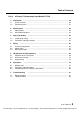
Table of Contents Table of Contents Safety Precautions ............................................................................................................ 1 About This Manual ............................................................................................................ 2 Part 1 1. 1.1 1.2 2. 2.1 2.2 3. 3.1 3.2 4. 4.1 4.2 4.3 5. 5.1 5.2 5.3 6. 6.1 6.2 6.3 7. 7.1 7.2 8 Channel Analog Input Module AD268 Introduction …………….……………………………………………………………….… 8 AD268 functions ............
Table of Contents Part 2 1. 1.1 1.2 2. 2.1 2.2 3. 3.1 4. 4.1 4.2 4.3 5. 5.1 5.2 5.3 6. 6.1 6.2 7. 7.1 7.2 4 4 Channel Analog Output Module DA264 Introduction …………….……………………………………………………………….… 36 DA264 functions ............………………..…………………….………………………… 36 External features …......…………………………………………………………………. 37 Specifications ….………………………………………………………………………... 38 Specifications .................…………….……………………………………………….. 38 Internal block diagram ………….......………………………………………………… 39 Output Type Setting ….........
Table of Contents Part 3 1. 1.1 1.2 2. 2.1 2.2 3. 3.1 3.2 4. 4.1 4.2 4.3 5. 5.1 5.2 5.3 6. 6.1 6.2 6.3 7. 7.1 7.2 8 Channel Thermocouple Input Module TC218 Introduction …………….……………………………………………………………….… 60 TC218 functions ............………………..…………………….………………………… 60 External features …......…………………………………………………………………. 61 Specifications ….………………………………………………………………………... 62 Specifications .................…………….……………………………………………….. 62 Internal block diagram ………….......
6 Analog I/O Modules (AD268 / DA264 / TC218) CTi Automation - Phone: 800.894.0412 - Fax: 208.368.0415 - Web: www.ctiautomation.net - Email: info@ctiautomation.
Part 1 8 Channel Analog Input Module AD268 1. 2. 3. 4. 5. 6. 7. Introduction, 8 Specifications, 10 Input Type Setting, 12 Wiring, 14 I/O Allocation and Programming, 17 Parameters, 24 Troubleshooting, 32 User’s Manual 7 CTi Automation - Phone: 800.894.0412 - Fax: 208.368.0415 - Web: www.ctiautomation.net - Email: info@ctiautomation.
1. Introduction PART 1 AD268 1. Introduction The AD268 is an 8 channel analog input module for the T2 series programmable controllers. The AD268 converts external analog signals (voltage or current) into digital values cyclically so that the T2 can process the analog signals. 1.1 AD268 Functions The AD268 has the following functions.
1. Introduction PART 1 AD268 1.2 External features Model type AD268 Status indication LED Removable terminal block Analog input terminal External power supply connection terminal Line ground and Frame ground terminal Terminal block fixing screw 2-points User’s Manual 9 CTi Automation - Phone: 800.894.0412 - Fax: 208.368.0415 - Web: www.ctiautomation.net - Email: info@ctiautomation.
2. Specifications PART 1 AD268 2. Specifications This section describes the AD268 specifications. The general specification for the AD268 conforms to the specification for the T2 PLC. 2.
2. Specifications PART 1 AD268 2.2 Internal block diagram Jumper 1 3 Internal control circuit A/D conversion LED Multiplexer CH1 N Buffer Filter P 2 T2 CPU Jumper 1 Optical isolation CH8 N Buffer Filter P 2 3 COM DC/DC converter P24 Filter Regulator +5V +15V AG -15V LG FG EEPROM Voltage check circuit The AD268 performs the following operations. The external analog signals come to the buffer amplifier through the filter.
3. Input Type Setting PART 1 AD268 3. Input Type Setting The AD268 supports multiple input ranges, ±5V, ±10V, 0 to 5V, 0 to 10V, 1 to 5V, 0 to 20mA, or 4 to 20mA. The input range is selected by jumper plug setting and the parameter writing by the T2 program. The general flow for setting the input type is as follows. (1) Set the jumper plugs to select voltage input or current input. (2) Mount the AD268 onto the T2 rack. (3) Turn on power to the T2 system. (4) Execute I/O allocation.
3. Input Type Setting PART 1 AD268 3.2 Parameter setting by software The input range of the AD268 is specified by writing the following parameter data into the AD268's buffer memory. To access the buffer memory, T2 user program (READ and WRITE instructions) is required. When the parameter is set to the AD268, it is saved in the AD268's built-in EEPROM. Therefore, once the input type parameter is set, there is no need to execute the input type setting operation.
4. Wiring PART 1 AD268 4. Wiring 4.1 Terminal arrangement AD268 terminal block 1N 2 2N 4 3N 6 4N 8 5N 10 6N 12 7N 14 8N 16 COM 18 FG 20 Terminal No.
4. Wiring PART 1 AD268 4.
4. Wiring PART 1 AD268 4.3 Wiring precautions (1) Use shielded twisted-pair cables for analog input signal lines and wire them in shortest distance. Connect the cable shield to ground in shortest distance for EMC conformity. Normally the grounding method (a) is recommended. However, depending on the condition, method (b) or (c) may be useful for stable operation.
5. I/O Allocation and Programming PART 1 AD268 5. I/O Allocation and Programming 5.1 Allocation to the T2 registers The I/O type of the AD268 is "X 8W". When the automatic I/O allocation operation is performed with a AD268 mounted on the rack, the AD268 is allocated as "X 8W". The AD268 occupies the 8 consecutive input (XW) registers of the T2. In this manual, these assigned I/O registers are expressed as XW(n), XW(n+1), ... XW(n+7).
5. I/O Allocation and Programming PART 1 AD268 5.2 A/D conversion data The analog signals received by the AD268 are converted into the digital data in this module. These converted digital data are read by T2 CPU in the batch I/O processing and stored in the assigned input registers as follows. XW(n) ........ A/D conversion data for channel 1 XW(n+1) .... A/D conversion data for channel 2 XW(n+2) .... A/D conversion data for channel 3 XW(n+3) .... A/D conversion data for channel 4 XW(n+4) ....
5. I/O Allocation and Programming PART 1 AD268 ± 5V range: A/D conversion data Hexadecimal Integer H3FFF 16383 : : H3E80 16000 : : H0001 1 H0000 0 HFFFF -1 : : HC180 -16000 : : HC000 -16384 Input voltage Upper limit Full scale (positive) 0 Full scale (negative) Lower limit +5.1196 V : +5 V : +0.3125 mV 0V -0.3125 mV : -5 V : -5.12 V Digital value Upper limit H3E80 16000 Analog input 0 -5.12V HC180 -16000 Lower limit 0.3125 mV / bit +5V H3FFF 16383 -10.2V Resolution +5.
5. I/O Allocation and Programming PART 1 AD268 0 to 10V range: Input voltage Upper limit Full scale (positive) 0 +10.2 V : +10 V : +0.3125 mV 0V Digital value A/D conversion data Hexadecimal Integer H7F80 32640 : : H7D00 32000 : : H0001 1 H0000 0 Resolution 0.3125 mV / bit +10 H7D00 32000 H3FFF 16383 Analog input 0 -10.2V +5.1196V +10.2V D = 3200 × A D: Digital data A: Analog signal (V) 20 Analog I/O Modules (AD268 / DA264 / TC218) CTi Automation - Phone: 800.894.0412 - Fax: 208.368.
5. I/O Allocation and Programming PART 1 AD268 0 to 5V / 0 to 20mA range: Input voltage/current 0 to 5 V 0 to 20 mA +5.1196 V +20.479 mA : : +5 V +20 mA : : +0.3125 mV +0.00125 mA 0V 0 mA Upper limit Full scale (positive) 0 Digital value A/D conversion data Hexadecimal Integer H3FFF 16383 : : H3E80 16000 : : H0001 1 H0000 0 Resolution 0.3125 mV / bit 1.25 µA / bit +5V 20mA 0 to 5V range: H3FFF 16383 Lower limit -10.2V D = 3200 × A Upper limit H3E80 16000 Analog input 0 +5.1196V 20.
5. I/O Allocation and Programming PART 1 AD268 1 to 5V / 4 to 20mA range: Upper limit Full scale (positive) Lower limit Input voltage/current 1 to 5 V 4 to 20 mA +5.1196 V +20.479 mA : : +5 V +20 mA : : +1.0003125 V +4.00125 mA 1V 4 mA A/D conversion data Hexadecimal Integer H337F 13183 : : H3200 12800 : : H0001 1 H0000 0 +5V 20mA Digital value Resolution 0.3125 mV / bit 1.25 µA / bit 1 to 5V range: D = 3200 × A - 3200 H337F 13183 Lower limit -10.
5. I/O Allocation and Programming PART 1 AD268 5.3 Programming To read the A/D conversion data, there is no need to use special instruction. The A/D conversion data are automatically stored in the assigned input registers (XW registers). For example, when the AD268 is allocated to XW000 to XW007, the A/D conversion data of each channel is stored as follows.
6. Parameters PART 1 AD268 6. Parameters The AD268 has the memory that stores the control parameters, input type designation, module status information, etc. This memory is called the buffer memory. To access (read/write) this memory from the T2 program, READ and WRITE instructions are used. 6.1 Memory map The contents of the AD268's buffer memory are as follows.
6.
6. Parameters PART 1 AD268 Gain calibration value & Offset calibration value: (Gain: H8000 to H8007, Offset: H8008 to H800F) At the factory shipment, the AD268 is calibrated for each input range. Therefore, there is no need for user to calibrate normally. However, depending on the usage condition, field adjustments are required. For this purpose, the AD268 has the gain and offset calibration function. In the AD268, the A/D conversion data is calculated as follows.
6. Parameters PART 1 AD268 Averaging times: (H8010 to H8017) This parameter is for the averaging processing for the analog input data. The moving average is calculated by the given averaging times parameter. For example, if the averaging times parameter is 10, the average value of latest 10 times conversion is output as the A/D conversion data. This function is effective to reduce the fluctuation caused by noise. The available setting range is as follows.
6. Parameters PART 1 AD268 Command register: (H8020) This register is used to issue the following commands to the AD268. To issue the command, write the command value by using WRITE instruction. Value 0 Command - 1 Parameter set 2 Reset command Description Write 0 after the command processing is completed. When this command is issued, the parameters written into the buffer memory are saved in the AD268 ’s EEPROM, and the parameters become effective.
6. Parameters PART 1 AD268 Analog input actual value: (H8028 to H802F) These data show the original A/D conversion data before processing the gain and offset calibration. Module status: (H8030 to H8037) These data show the AD268’s operation status.
6. Parameters PART 1 AD268 6.2 Parameter setting procedure When you change the AD268 parameters, such as input type settings, gain/offset calibrations and averaging times, use the following procedure. Step (1) Write the value "0" into the command register of the AD268 buffer memory (address H8020) by WRITE instruction. H8020 Command register ← Write 0 Step (2) Write the parameter data into the buffer memory (addresses H8000 to H801F) by WRITE instruction. Be sure to write all the 32 words in batch.
6. Parameters PART 1 AD268 6.3 Sample program for setting the parameters A sample program to set the parameters is shown below. This is an example to set the input type as 0 to 10V range (type = 1) for each channel. In this sample program, it is assumed that he AD268 is allocated to XW000 to XW007. For details of READ and WRITE instructions, refer to the T-series Instruction Set manual. (Main program) (H8020) (H8000) (H8020) Step (1): Writes 0 into the command register (H8020).
7. Troubleshooting PART 1 AD268 7. Troubleshooting 7.1 RAS information The RUN LED is provided on the front of the AD268. When the AD268 is operating normally, this LED is lit. Also the module status information is provided in the AD268‘s buffer memory (addresses H8030 to H8037). This information is useful for troubleshooting. Module status: (H8030 to H8037) These data show the AD268’s operation status.
7. Troubleshooting PART 1 AD268 7.2 Troubleshooting The table below shows the trouble and its remedy.
34 Analog I/O Modules (AD268 / DA264 / TC218) CTi Automation - Phone: 800.894.0412 - Fax: 208.368.0415 - Web: www.ctiautomation.net - Email: info@ctiautomation.
Part 2 4 Channel Analog Output Module DA264 1. 2. 3. 4. 5. 6. 7. Introduction, 36 Specifications, 38 Output Type Setting, 40 Wiring, 41 I/O Allocation and Programming, 44 Parameters, 51 Troubleshooting, 56 User’s Manual 35 CTi Automation - Phone: 800.894.0412 - Fax: 208.368.0415 - Web: www.ctiautomation.net - Email: info@ctiautomation.
1. Introduction PART 2 DA264 1. Introduction The DA264 is a 4 channel analog output module for the T2 series programmable controllers. The DA264 converts digital values given by the T2 program into the analog signals (voltage or current). 1.1 DA264 Functions The DA264 has the following functions.
1. Introduction PART 2 DA264 1.2 External features Model type DA264 Status indication LED Removable terminal block Analog output terminal External power supply connection terminal Line ground and Frame ground terminal Terminal block fixing screw 2-points User’s Manual 37 CTi Automation - Phone: 800.894.0412 - Fax: 208.368.0415 - Web: www.ctiautomation.net - Email: info@ctiautomation.
2. Specifications PART 2 DA264 2. Specifications This section describes the DA264 specifications. The general specification for the DA264 conforms to the specification for the T2 PLC. 2.
2. Specifications PART 2 DA264 2.2 Internal block diagram Amplifier LED P D/A conversion Internal control circuit T2 CPU Buffer (V→V) N Voltage output Amplifier CH1 P TR (V→I) N Current output Amplifier Buffer Optical isolation P (V→V) N Voltage output Amplifier CH4 P TR (V→I) N Reference voltage +15V AG -15V Filter Regulator DC/DC converter +5V Current output P24 COM LG Voltage check circuit FG The DA264 performs the following operations.
3. Output Type Setting PART 2 DA264 3. Output Type Setting The DA264 supports multiple output ranges, ±5V, ±10V, 0 to 5V, 0 to 10V, 1 to 5V, 0 to 20mA, or 4 to 20mA. The output range is selected by writing the parameter into the DA264 by the T2 program. The voltage or current output is selected by the DA264’s output terminals. The general flow for setting the output type is as follows. (1) Mount the DA264 onto the T2 rack. (2) Turn on power to the T2 system. (3) Execute I/O allocation.
4. Wiring PART 2 DA264 4. Wiring 4.1 Terminal arrangement DA264 terminal block 1VN 2 1CN 4 2VN 6 2CN 8 3VN 10 3CN 12 4VN 14 4CN 16 COM 18 FG 20 Terminal No.
4. Wiring PART 2 DA264 4.2 Signal wiring Voltage output DA264 +15V Shielded twisted-pair cable nVP nVN -15V AG Internal circuit n : Channel number (1 to 4) AG : Analog ground Current output DA264 +15V +15V Shielded twisted-pair cable nCP nCN -15V AG n : Channel number (1 to 4) AG : Analog ground Internal circuit External 24Vdc power supply DA264 +15V P24 + DC/DC converter 24Vdc ±10% - COM AG -15V LG (a) FG Internal circuit 42 (b) Normally connect LG and FG , then connect to ground.
4. Wiring PART 2 DA264 4.3 Wiring precautions (1) Use shielded twisted-pair cables for analog output signal lines and wire them in shortest distance. Connect the cable shield to ground in shortest distance for EMC conformity. Normally the grounding method (a) is recommended. However, depending on the condition, method (b) or (c) may be useful for stable operation.
5. I/O Allocation and Programming PART 2 DA264 5. I/O Allocation and Programming 5.1 Allocation to the T2 registers The I/O type of the DA264 is "Y 4W". When the automatic I/O allocation operation is performed with a DA264 mounted on the rack, the DA264 is allocated as "Y 4W". The DA264 occupies the 4 consecutive output (YW) registers of the T2. In this manual, these assigned I/O registers are expressed as YW(n), YW(n+1), YW(n+2) and YW(n+3).
5. I/O Allocation and Programming PART 2 DA264 5.2 D/A conversion data To output the desired analog signals from the DA264, simply write the appropriate data into the assigned I/O registers YW(n) to YW(n+3) for the DA264. The data of YW(n) to YW(n+3) are transferred to the DA264 at the T2’s batch I/O processing. Then in the DA264, these D/A conversion data are converted into the analog signals and output from the DA264. The I/O register assignment is as follows. YW(n) ........
5. I/O Allocation and Programming PART 2 DA264 ± 5V range: Upper limit Full scale (positive) 0 Full scale (negative) Lower limit D/A conversion data Hexadecimal Integer H3FFF 16383 : : H3E80 16000 : : H0001 1 H0000 0 HFFFF -1 : : HC180 -16000 : : HC000 -16384 Output voltage Resolution +5.1196 V : +5 V : +0.3125 mV 0V -0.3125 mV : -5 V : -5.12 V 0.3125 mV / bit Analog output value H3E80 16000 Upper limit +5.
5. I/O Allocation and Programming PART 2 DA264 0 to 10V range: Upper limit Full scale (positive) 0 D/A conversion data Hexadecimal Integer H7F80 32640 : : H7D00 32000 : : H0001 1 H0000 0 Output voltage Resolution +10.2 V : +10 V : +0.3125 mV 0V 0.3125 mV / bit Analog output value +10V H7D00 32000 Lower limit H8000 -32768 0 Digital data H7FFF 32767 A = 0.3125 × D D: Digital data A: Analog signal (mV) User’s Manual 47 CTi Automation - Phone: 800.894.0412 - Fax: 208.368.0415 - Web: www.
5. I/O Allocation and Programming PART 2 DA264 0 to 5V / 0 to 20mA range: Upper limit Full scale (positive) 0 D/A conversion data Hexadecimal Integer H3FFF 16383 : : H3E80 16000 : : H0001 1 H0000 0 Output voltage/current 0 to 5 V 0 to 20 mA +5.1196 V +20.479 mA : : +5 V +20 mA : : +0.3125 mV +0.00125 mA 0V 0 mA Analog output value Lower limit H8000 -32768 0 0.3125 mV / bit 1.25 µA / bit 0 to 5V range: H3E80 16000 +5.1196V (+20.478mA) Resolution Upper limit +5V (+20mA) A = 0.
5. I/O Allocation and Programming PART 2 DA264 1 to 5V / 4 to 20mA range: Upper limit Full scale (positive) 0 Lower limit D/A conversion data Hexadecimal Integer H337F 13183 : : H3200 12800 : : H0001 1 H0000 0 : : HF380 -3200 H3200 12800 Analog output value Output voltage/current 1 to 5 V 4 to 20 mA +5.1196 V +20.479 mA : : +5 V +20 mA : : +1.0003125 V +4.00125 mA 1V 4 mA : : 0V 0 mA H337F 13183 Resolution 0.3125 mV / bit 1.25 µA / bit 1 to 5V range: A = 0.
5. I/O Allocation and Programming PART 2 DA264 5.3 Programming To output the desired analog signal from the DA264, there is no need to use any special instruction. When the D/A conversion data is written in the assigned output register (YW register), it is transferred to the DA264 and converted to the corresponding analog signal. For example, when the DA264 is allocated to YW000 to YW003, the D/A conversion data of each channel is assigned as follows.
6. Parameters PART 2 DA264 6. Parameters The DA264 has the memory that stores the control parameters, output type designation, module status information, etc. This memory is called the buffer memory. To access (read/write) this memory from the T2 program, READ and WRITE instructions are used. These parameter data are not maintained in the DA264. Therefore, you should write the necessary parameter data at each time of the beginning of the operation. 6.
6. Parameters PART 2 DA264 Offset calibration value: (H8000 to H8003) At the factory shipment, the DA264 is calibrated for each output range. Therefore, there is no need for user to calibrate normally. However, depending on the usage condition, field adjustments are required. For this purpose, the DA264 has the offset calibration function. In the DA264, the D/A conversion is performed as follows.
6. Parameters PART 2 DA264 Output type setting: (H8004 to H8007) This parameter is used to select the output type. This parameter also has a function to select either clear or hold the analog output signal in case of the T2 operation stop (Halt or Error). The available setting range is as follows. Output type 0 to 5V 0 to 10V 1 to 5V ±5V ±10V 0 to 20mA 4 to 20mA - Setting value Clear mode Hold mode 0 160 1 161 2 162 4 164 5 165 The default setting value (factory setting) is 0 (0 to 5V/0 to 20mA).
6. Parameters PART 2 DA264 Analog output read-back value: (H8008 to H800B) These data show the D/A conversion data after processing the offset calibration. Module status: (H800C to H800F) These data show the DA264’s operation status. Bit position → F E 0 Bit 0 to 2 Name Output type 3 to 4 5 to 7 Hold mode 8 Output type setting error Output limit 9 to C D E F 54 D C B A 9 0 0 0 0 External 24V error - 8 7 6 5 4 3 0 0 2 1 0 Description Shows the output type.
6. Parameters PART 2 DA264 6.2 Sample program to access the parameters To write the parameters into the DA264’s buffer memory, use the WRITE instruction. No special procedure is required. To read the parameters from the DA264’s buffer memory, use the READ instruction. A sample program to write/read the parameters is shown below. This is an example to set the output type as ±10V range (type = 5) for each channel. In this sample program, it is assumed that he DA264 is allocated to YW000 to YW003.
7. Troubleshooting PART 2 DA264 7. Troubleshooting 7.1 RAS information The RUN LED is provided on the front of the DA264. When the DA264 is operating normally, this LED is lit. Also the module status information is provided in the DA264‘s buffer memory (addresses H800C to H800F). This information is useful for troubleshooting. Refer to section 6 for the module status information and how to read it. 7.2 Troubleshooting The table below shows the trouble and its remedy.
User’s Manual 57 CTi Automation - Phone: 800.894.0412 - Fax: 208.368.0415 - Web: www.ctiautomation.net - Email: info@ctiautomation.
58 Analog I/O Modules (AD268 / DA264 / TC218) CTi Automation - Phone: 800.894.0412 - Fax: 208.368.0415 - Web: www.ctiautomation.net - Email: info@ctiautomation.
Part 3 8 Channel Thermocouple Input Module TC218 1. 2. 3. 4. 5. 6. 7. Introduction, 60 Specifications, 62 Input Type Setting, 64 Wiring, 66 I/O Allocation and Programming, 69 Parameters, 75 Troubleshooting, 83 User’s Manual 59 CTi Automation - Phone: 800.894.0412 - Fax: 208.368.0415 - Web: www.ctiautomation.net - Email: info@ctiautomation.
1. Introduction PART 3 TC218 1. Introduction The TC218 is a thermocouple input module for the T2 series programmable controllers. The TC218 is used to measure the temperature using thermocouples. Thermocouples type K, J, or E can be used. The TC218 can be used for ±100mV input also. When the TC218 is used for the thermocouple input, it has 7 channels of thermocouple input. The remaining 1 channel is used to measure the ambient temperature for cold junction compensation.
1. Introduction PART 3 TC218 1.2 External features Model type TC218 Status indication LED Removable terminal block Analog input terminal External power supply connection terminal Line ground and Frame ground terminal Terminal block fixing screw 2-points For thermocouple input, CH2 to CH8 are used to connect the thermocouple input wires. The CH1 is used to connect the thermistor to measure the ambient temperature for cold junction compensation. For ±100mV input, all 8 channels CH1 to CH8 are used.
2. Specifications PART 3 TC218 2. Specifications This section describes the TC218 specifications. The general specification for the TC218 conforms to the specification for the T2 PLC. 2.
2. Specifications PART 3 TC218 2.2 Internal block diagram Reference voltage Buffer LED 3 N +15V 1 2 CH2 +15V 1 2 CH8 N Buffer Filter Jumper P DC/DC converter Filter COM +5V +15V AG -15V LG FG EEPROM 3 Regulator P24 T2 CPU 3 N Optical isolation P Buffer Filter Jumper Internal control circuit CH1 A/D conversion 2 Multiplexer P 1 Filter Jumper Voltage check circuit The TC218 performs the following operations.
3. Input Type Setting PART 3 TC218 3. Input Type Setting The TC218 supports multiple input types, type K, type J, type E, or ±100mV. The input type is selected by jumper plug setting and the parameter writing by the T2 program. Note that the input type can be selected either one, type K, type J, type E, or ±100mV, for all channels. Any mixture settings among the channels are not allowed. The general flow for setting the input type is as follows.
3. Input Type Setting PART 3 TC218 3.2 Parameter setting by software The input type of the TC218 is specified by writing the following parameter data into the TC218's buffer memory. To access the buffer memory, T2 user program (READ and WRITE instructions) is required. When the parameter is set to the TC218, it is saved in the TC218's built-in EEPROM. Therefore, once the input type parameter is set, there is no need to execute the input type setting operation.
4. Wiring PART 3 TC218 4. Wiring 4.1 Terminal arrangement TC218 terminal block 1N 2 2N 4 3N 6 4N 8 5N 10 6N 12 7N 14 8N 16 COM 18 FG 20 Terminal No.
4. Wiring PART 3 TC218 4.
4. Wiring PART 3 TC218 External 24Vdc power supply TC218 +15V 24Vdc ±10% P24 + DC/DC converter - COM AG -15V LG (b) (a) Normally connect LG and FG , then connect to ground. (a) However, depending on the condition, connect grounding individually by opening LG and FG. (b) FG Internal circuit 4.3 Wiring precautions (1) The thermocouple signal is weak voltage. Pay attention to prevent noise interference.
5. I/O Allocation and Programming PART 3 TC218 5. I/O Allocation and Programming 5.1 Allocation to the T2 registers The I/O type of the TC218 is "X 8W". When the automatic I/O allocation operation is performed with a TC218 mounted on the rack, the TC218 is allocated as "X 8W". The TC218 occupies the 8 consecutive input (XW) registers of the T2. In this manual, these assigned I/O registers are expressed as XW(n), XW(n+1), ... XW(n+7).
5. I/O Allocation and Programming PART 3 TC218 5.2 A/D conversion data The analog signals received by the TC218 are converted into the digital data in this module. These converted digital data are read by T2 CPU in the batch I/O processing and stored in the assigned input registers as follows. XW(n) ........ A/D conversion data for channel 1 XW(n+1) .... A/D conversion data for channel 2 XW(n+2) .... A/D conversion data for channel 3 XW(n+3) .... A/D conversion data for channel 4 XW(n+4) ....
5. I/O Allocation and Programming PART 3 TC218 Thermocouple (type K) input: Burnout detection Upper limit Full scale (positive) 0 Full scale (negative) Lower limit Input temperature +1370 °C : +1200 °C : +0.05 °C 0V -0.05 °C : -200 °C : -270 °C A/D conversion data Hexadecimal Integer H7FFF 32767 H6B08 27400 : : H5DC0 24000 : : H0001 1 H0000 0 HFFFF -1 : : HF060 -4000 : : HEAE8 -5400 Resolution 0.
5. I/O Allocation and Programming PART 3 TC218 Thermocouple (type J) input: Burnout detection Upper limit Full scale (positive) 0 Full scale (negative) Lower limit Input temperature +1200 °C : +800 °C : +0.05 °C 0V -0.05 °C : -200 °C : -210 °C A/D conversion data Hexadecimal Integer H7FFF 32767 H5DC0 24000 : : H3E80 16000 : : H0001 1 H0000 0 HFFFF -1 : : HF060 -4000 : : HEF98 -4200 Resolution 0.
5. I/O Allocation and Programming PART 3 TC218 Thermocouple (type E) input: Burnout detection Upper limit Full scale (positive) 0 Full scale (negative) Lower limit Input temperature +1000 °C : +600 °C : +0.05 °C 0V -0.05 °C : -200 °C : -270 °C A/D conversion data Hexadecimal Integer H7FFF 32767 H4E20 20000 : : H2EE0 12000 : : H0001 1 H0000 0 HFFFF -1 : : HF060 -4000 : : HEAE8 -5400 Resolution 0.
5. I/O Allocation and Programming PART 3 TC218 5.3 Programming To read the A/D conversion data, there is no need to use special instruction. The A/D conversion data are automatically stored in the assigned input registers (XW registers). For example, when the TC218 is allocated to XW000 to XW007, the A/D conversion data of each channel is stored as follows.
6. Parameters PART 3 TC218 6. Parameters The TC218 has the memory that stores the control parameters, input type designation, module status information, etc. This memory is called the buffer memory. To access (read/write) this memory from the T2 program, READ and WRITE instructions are used. 6.1 Memory map The contents of the TC218's buffer memory are as follows.
6.
6. Parameters PART 3 TC218 Gain calibration value & Offset calibration value: (± ± 100mV input only) (Gain: H8000 to H8007, Offset: H8008 to H800F) For the ±100mV input, the gain and offset calibration is possible. In the TC218, the A/D conversion data is calculated as follows.
6. Parameters PART 3 TC218 Averaging times: (H8010 to H8017) This parameter is for the averaging processing for the analog input data. The moving average is calculated by the given averaging times parameter. For example, if the averaging times parameter is 100, the average value of latest 100 times conversion is output as the A/D conversion data. This function is effective to reduce the fluctuation caused by noise. The available setting range is as follows.
6. Parameters PART 3 TC218 Command register: (H8020) This register is used to issue the following commands to the TC218. To issue the command, write the command value by using WRITE instruction. Value 0 Command - 1 Parameter set 2 Reset command Description Write 0 after the command processing is completed. When this command is issued, the parameters written into the buffer memory are saved in the TC218 ’s EEPROM, and the parameters become effective.
6. Parameters PART 3 TC218 Analog input actual value: (H8028 to H802F) These data show the original A/D conversion data before processing the gain and offset calibration. Module status: (H8030 to H8037) These data show the TC218’s operation status.
6. Parameters PART 3 TC218 6.2 Parameter setting procedure When you change the TC218 parameters, such as input type settings, gain/offset calibrations and averaging times, use the following procedure. Step (1) Write the value "0" into the command register of the TC218 buffer memory (address H8020) by WRITE instruction. H8020 Command register ← Write 0 Step (2) Write the parameter data into the buffer memory (addresses H8000 to H801F) by WRITE instruction. Be sure to write all the 32 words in batch.
6. Parameters PART 3 TC218 6.3 Sample program for setting the parameters A sample program to set the parameters is shown below. This is an example to set the input type as the type J thermocouple (type = 1) for each channel. In this sample program, it is assumed that he TC218 is allocated to XW000 to XW007. For details of READ and WRITE instructions, refer to the T-series Instruction Set manual. (Main program) (H8020) (H8000) (H8020) Step (1): Writes 0 into the command register (H8020).
7. Troubleshooting PART 3 TC218 7. Troubleshooting 7.1 RAS information The RUN LED is provided on the front of the TC218. When the TC218 is operating normally, this LED is lit. Also the module status information is provided in the TC218‘s buffer memory (addresses H8030 to H8037). This information is useful for troubleshooting. Module status: (H8030 to H8037) These data show the TC218’s operation status.
7. Troubleshooting PART 3 TC218 7.2 Troubleshooting The table below shows the trouble and its remedy.