FILE NO.
FILE NO. SVM-06012 CONTENTS 1. SPECIFICATIONS............................................................................................................. 1 2. CONSTRUCTION VIEWS ................................................................................................. 3 3. SYSTEMATIC REFRIGERATING CYCLE DIAGRAM ...................................................... 4 4. WIRING DIAGRAM ........................................................................................................... 5 5.
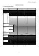
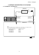
FILE NO. SVM-06012 1. SPECIFICATIONS 1-1. Indoor Unit (Flexi Type) Model Indoor unit RAV-SM562XT-E RAV-SM802XT-E Outdoor unit RAV-SM562AT-E RAV-SM802AT-E Cooling capacity Heating capacity (kW) 5.0 6.7 (kW) 5.6 8.0 Power supply Electrical characteristics 1 phase 230V (220-240V) 50Hz Cooling Running current 8.95-8.20 (A) Power consumption Power factor EER (kW) 2.72 (%) 95 94 2.67 2.46 D E (W/W) Energy efficiency class * 2.5 1.5 (A) 8.13-7.46 12.91-11.84 (kW) 1.70 2.
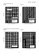
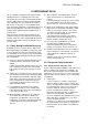
FILE NO. SVM-06012 • Operation characteristic curve 14 12 14 RAV-SM802XT-E RAV-SM802XT-E 12 10 Current (A) Current (A) 10 8 6 8 6 RAV-SM562XT-E 4 RAV-SM562XT-E 4 • Conditions Indoor : DB27˚C/WB19˚C Outdoor : DB35˚C Air flow : High Pipe length : 7.
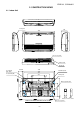
FILE NO. SVM-06012 2. CONSTRUCTION VIEWS 2-1.
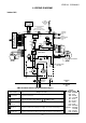
FILE NO. SVM-06012 3. SYSTEMATIC REFRIGERATING CYCLE DIAGRAM 3-1. RAV-SM562XT-E / RAV-SM802XT-E Indoor unit TCJ sensor Air heat exchanger TC sensor Model Outer diameter of refrigerant pipe RAV-SM Gas side ∅A 562XT-E 12.7 mm Liquid side ∅ B 6.4 mm 802XT-E 15.9 mm 9.5 mm Refrigerant pipe at liquid side Outer dia. ∅B Refrigerant pipe at gas side Outer dia. ∅A Max 30m Packed valve Outer dia. ∅B Outdoor unit Packed valve Outer dia.
FILE NO. SVM-06012 4.
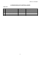
FILE NO. SVM-06012 5. SPECIFICATION OF ELECTRICAL PARTS Indoor Unit No. Parts name Type AFP-220-50-4A Specifications 1 Fan motor (for indoor) 2 Grille motor MP35EA DC 12 V 3 Thermo.
FILE NO. SVM-06012 6. REFRIGERANT R410A This air conditioner adopts the new refrigerant HFC (R410A) which does not damage the ozone layer. The working pressure of the new refrigerant R410A is 1.6 times higher than conventional refrigerant (R22).
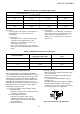
FILE NO. SVM-06012 Table 6-2-1 Thicknesses of annealed copper pipes Thickness (mm) Nominal diameter Outer diameter (mm) R410A R22 1/4 6.35 0.80 0.80 3/8 9.52 0.80 0.80 1/2 12.70 0.80 0.80 5/8 15.88 1.00 1.00 (2) Joints For copper pipes, flare joints or socket joints are used. Prior to use, be sure to remove all contaminants. a) Flare joints Flare joints used to connect the copper pipes cannot be used for pipings whose outer diameter exceeds 20 mm.
FILE NO. SVM-06012 Table 6-2-3 Dimensions related to flare processing for R410A A (mm) Outer diameter (mm) Thickness (mm) 1/4 6.35 3/8 Nominal diameter Conventional flare tool Flare tool for R410A clutch type Clutch type Wing nut type 0.8 0 to 0.5 1.0 to 1.5 1.5 to 2.0 9.52 0.8 0 to 0.5 1.0 to 1.5 1.5 to 2.0 1/2 12.70 0.8 0 to 0.5 1.0 to 1.5 2.0 to 2.5 5/8 15.88 1.0 0 to 0.5 1.0 to 1.5 2.0 to 2.
FILE NO. SVM-06012 45° 6° to 4 43° to 4 5° Fig. 6-2-2 Relations between flare nut and flare seal surface (2) Flare connecting procedures and precautions a) Make sure that the flare and union portions do not have any scar or dust, etc. When it is strong, the flare nut may crack and may be made non-removable. When choosing the tightening torque, comply with values designated by manufacturers. Table 6-2-7 shows reference values. b) Correctly align the processed flare surface with the union axis.
FILE NO. SVM-06012 6-3. Tools 6-3-1. Required tools The service port diameter of packed valve of the outdoor unit in the air conditioner using R410A is changed to prevent mixing of other refrigerant. To reinforce the pressure-resisting strength, flare processing dimensions and opposite side dimension of flare nut (For ∅12.70 copper pipe) of the refrigerant piping are lengthened.
FILE NO. SVM-06012 6-4. Recharging of Refrigerant When it is necessary to recharge refrigerant, charge the specified amount of new refrigerant according to the following steps. Recover the refrigerant, and check no refrigerant remains in the equipment. When the compound gauge’s pointer has indicated -0.1 Mpa (-76 cmHg), place the handle Low in the fully closed position, and turn off the vacuum pump’s power switch. Connect the charge hose to packed valve service port at the outdoor unit’s gas side.
FILE NO. SVM-06012 1 Be sure to make setting so that liquid can be charged. 2 When using a cylinder equipped with a siphon, liquid can be charged without turning it upside down. It is necessary for charging refrigerant under condition of liquid because R410A is mixed type of refrigerant. Accordingly, when charging refrigerant from the refrigerant cylinder to the equipment, charge it turning the cylinder upside down if cylinder is not equipped with siphon.
FILE NO. SVM-06012 (2) Characteristics required for flux • Activated temperature of flux coincides with the brazing temperature. • Due to a wide effective temperature range, flux is hard to carbonize. • It is easy to remove slag after brazing. • The corrosive action to the treated metal and brazing filler is minimum. • It excels in coating performance and is harmless to the human body.
FILE NO. SVM-06012 7. CONTROL BLOCK DIAGRAM Indoor Unit Control Panel M.C.U. 8 MHz Heat Exchanger Sensor (TCJ) Heat Exchanger Sensor (TC) Temperature Sensor Initiallizing Circuit 36.7 kHz Hi POWER Display • 3-minute Delay at Restart for Compressor FILTER Sign Display • Motor Revolution Control Infrared Rays Signal Receiver Infrared Rays Functions • Louver Control PRE DEF.
FILE NO. SVM-06012 8. OPERATION DESCRIPTION 8-1. When power supply is reset 8-3. Air volume control (1) Distinction of outdoor units When the power supply is reset, the outdoors are distinguished, and control is exchanged according to the distinguished result. (1) Operation with [HIGH (H)], [MED (M)], [LOW (L)], or [AUTO] mode is performed by the command from the remote control. (2) Setting of the indoor fan speed Based on EEPROM data, rspeed of the indoor fan is selected.
FILE NO. SVM-06012 8-4. Cool air discharge preventive control (Room temp.) − (Preset temp.) Preset temp. °C 0 −0.5 −1 −1.5 −2 In heating operation, the indoor heat exchanger restricts revolving speed of the fan motor to prevent a cold draft. The upper limit of the revolving speed is shown in Fig. 8-4-1 and Table 8-4-1. L *1 *2 −5.0 −5.5 [FAN AUTO] Fig.
FILE NO. SVM-06012 8-5. Freeze preventive control (Low temperature release) 8-7. Louver control The cooling operation (including Dry operation) is performed as follows based on the detected temperature of Tc sensor or Tcj sensor. When [J] zone is detected for T1 minutes (Following figure), the commanded frequency is decreased from the real operation frequency. After then the commanded frequency changes every 2 minutes while operation is performed in [J] zone.
FILE NO. SVM-06012 8-9. Auto Restart Function 8-9-1. How to set auto restart function The indoor unit is equipped with an automatic restarting function which allows the unit to restart operating with the set operating conditions in the event of power supply being accidentally shut down. The operation will resume without warning three minutes after power is restored. This function is not set to work when shipped from the factory. Therefore it is necessary to set it to work.
FILE NO. SVM-06012 8-9-2. How to cancel auto restart function To cancel auto restart function, proceed as follows: Repeat the setting prodedure: the unit receives the signal and beeps three times. The unit will be required to be turned on with the remote control after the main power supply is turned off. When the unit is on standby (Not operating) Operation Motions The unit is on standby. → Push [TEMPORARY] button for more than three seconds. The unit starts to operate.
FILE NO. SVM-06012 9. TROUBLESHOOTING 9-1. Summary of Troubleshooting 9-1-2. Troubleshooting procedure 9-1-1. Before troubleshooting When a trouble occurred, check the parts along with the following procedure. (1) Required tools/instruments • e and d screwdrivers, spanners, radio cutting pliers, nippers, etc. • Tester, thermometer, pressure gauge, etc. (2) Confirmation points before check 1 The following operations are normal. a) Compressor does not operate.
FILE NO. SVM-06012 9-2. Self-Diagnosis by Remote Control (Check Code) (1) If the lamps are indicated as shown 00 to 03 in Table 9-1-1, exchanger the self-diagnosis by the remote control. (2) When the remote control is set to the service mode, the indoor controller diagnoses the operation condition and indicate the information of the self-diagnosis on the display of the remote control with the check codes.
FILE NO. SVM-06012 Table 9-2-1 Operation of diagnostic function Check code Block Check code Unit status Symptom Condition Judgement and action The indoor thermo sensor (TA) is defective. Disconnection or short-circuit Operation continues. The lamp on the indoor unit blinks when error is defected. 1. Check the indoor thermo sensor (TA). 2. Check the indoor P.C. board. The indoor heat exchanger sensor (TC) is defective. Disconnection or short-circuit Operation continues.
FILE NO. SVM-06012 Table 9-2-2 Operation of diagnostic function Block Check code [MODE] [TIMER] lamp 5Hz flash Unit status Symptom Condition The serial signal is not output from outdoor unit to indoor unit. • Miscabling of inter-unit cables • Defective serial sending circuit on outdoor P.C. board • Defective serial receiving circuit on outdoor P.C. board • Compressor case thermo operation Operation continues. Displayed when error is detected 1. Outdoor unit does not completely operate.
FILE NO. SVM-06012 Table 9-2-3 Operation of diagnostic function Check code Symptom Unit status Condition Judgement and action Inverter over-current protective circuit operates. (For a short time) All stop Displayed when error is detected 1. Inverter immediately stops even if restarted. • Compressor rare short 2. Check IPDU. • Cabling error Error on current detection circuit • Current value is high at AC side even while compressor stops. • Phase of power supply is missed.
FILE NO.
FILE NO. SVM-06012 10. DETACHMENTS 10-1. Indoor Unit No. 1 Part name Air Inlet grille Procedures Remarks 1) Stop the operation of the Air conditioner and turn off its main power supply. 2) Open the Air inlet grille with both hands. Air inlet grille 3) Unfasten 3 screws (about two to three rounds) for fixing the Panel arms. 4) Move the Air inlet grille toward. Panel arm 5) Remove the Grille stopper from the axis of the Front panel.
FILE NO. SVM-06012 No. 2 Part name Front panel Procedures Remarks 1) Remove the Air inlet grille. (1) 2) In case of the Drain hose is installed through the Front panel. : Remove the Drain band from the Front panel. : Cut away the Opening base for piping from Front panel and keep parts. Drain band 3) Open 3 Cap screws and remove the screws. Drain panel Cap screws Front Panel 4) Remove 5 screws fixing the Front panel.
FILE NO. SVM-06012 No. 2 Part name Front panel Procedures Remarks 6) Remove both side hooks and remove the Front panel by turn to air inlet part direction. Hook 1) In case of the Drain hose installation through the Front panel, install the opening base for piping in the Back body by a screw (M4 x 12). Prepare it by yourself. 2) Fit the Front panel in the Drain pan. Then fix it in the Drain pan with 2 hooks in the center of the air outlet.
FILE NO. SVM-06012 No. 3 Part name Drain pan assembly Procedures Remarks Screw 7) Remove 7 screws and remove the Drain pan assembly. Drain Pan Screw 4 Electrical parts assembly Refrigeration 1) Remove the Air inlet grille, the Front panel TC sensor assembly and the Drain pan assembly. (1, 2, 3) Connecting cable Cord clamp Earth wire 2) Remove the Terminal cover. 3) Unfasten the screw of Cord clamp and TCJ disconnect the connecting cable.
FILE NO. SVM-06012 No. 5 Part name Refrigeration assembly Procedures Remarks 7) Remove 2 screws and remove the refrigeration assembly with pushing it to right hand. 2 Screws 6 Multiblade fan and Fan motor 1) Remove the Air inlet grille and the Front panel. (1, 2) 2) Disconnect 2 connectors. 3) Remove the Fan covers. 4) Remove the Motor band with holding the Fan motor and then remove the Fan motor with the Multi-blade fans.
FILE NO. SVM-06012 11. EXPLODED VIEWS AND PARTS LIST 11-1. Indoor Unit (E-Parts Assy) 401 403 402 404 405 407 408 Location No. Part No. Description Location No. 406 Part No.
FILE NO. SVM-06012 11-2. Indoor Unit 220 222 217 218 227 224 214 208 207 223 208 216 212 203 235 206 219 204 225 202 221 226 213 210 211 229 209 215 233 228 231 234 235 201 205 230 232 Location No. Part No. Description Location No. Part No.
TOSHIBA CARRIER (THAILAND) CO., LTD. 144/9 MOO 5, BANGKADI INDUSTRIAL PARK, TIVANON ROAD, TAMBOL BANGKADI, AMPHUR MUANG, PATHUMTHANI 12000, THAILAND.