
user manual


– 137 –
No.
Part name
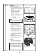
Ceiling panel
Procedure
1. Detachment
1) Carry out works of item 1 of
and item 1
of
.
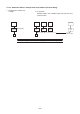
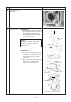
2) Remove the flap connector
(CN510, White, 20P) connected to the
control P.C. board and then remove the
lead wire from the clamp.
NOTE :
Unlock the lock of the housing part and
then remove the connector.
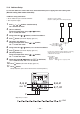
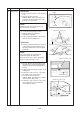
3) Loosen the panel fixing 4 screws.
4) Slide the panel fixing brackets
(4 positions) outward.
5) Push the tentative bracket outward and
then remove the ceiling panel.
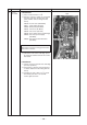
2. Attachment
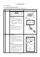
1) Insert the tentative brackets (2 positions)
of the ceiling panel into square holes of
the indoor unit and then hook the panel
tentatively.
NOTE :
The ceiling panel has the directional
properties against the indoor unit.
Direct the louver motor wire to the electric
parts box side of the indoor unit.
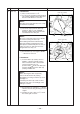
2) Pass the head of the panel fixing screw
through hole of the panel fixing bracket
and then slide the panel fixing bracket
inward.
3) Tighten in the panel fixing screw to fix the
ceiling panel.
4) Following to work of item 2 of
, attach
the adjust corner cap as before.
5) Connect the louver connector
(CN510, White, 20P) as before and then
fix the lead wire with clamp.
6) Following to work of item 2 of
, mount
the electric parts box cover and the
suction grille as before.
Remarks
Clamp
CN510
Square hole of indoor unit
Panel fixing screw
Electric parts box
Louver motor wiring
Louver motor wiring
Tentative bracket Ceiling panel
Square hole of indoor unit
Square hole of indoor unit
Sliding direction
Panel fixing screw
Panel fixing bracket
Inner side
Outer side
Sliding direction
Panel fixing screw
Panel fixing bracket
Inner side
Outer side
Push in case
of removing
Push in case
of removing
Tentative bracket
Louver motor wiring
Louver motor wiring