
user manual

– 143 –
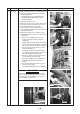
No.
Part name
Float switch
assembly
Procedure
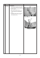
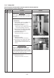
1. Detachment
1) Carry out works of item 1 of
and works
from 1) to 5).
2) Remove the fixing screw and then remove
the float switch assembly. (Ø4 × 25, 1 pc.)
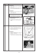
2. Attachment
1) Mount the float switch assembly as before
with the fixing screw.
NOTE :
When mounting, match hole of the float switch
assembly with projection of the drain pan.
2) Mount the bell mouth as before.
(Ø4 × 10, 8 pcs.)
3) Following to works of item 2 of
and
works from 2) to 5), attach the parts as
before.
Remarks
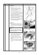
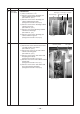
Float switch assembly
Fixing screw (Ø4 × 25)
Hole of float switch assembly
Projection of drain pan
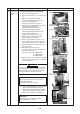
Float switch assembly
Fixing screw (Ø4 × 25)
Projection of drain pan
Fixing screws (Ø4 ×10)
Fixing screws (Ø4 ×10)Fixing screws (Ø4 ×10)
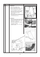
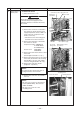
1. Detachment
1) Carry out works of item 1 of
, item 1 of
, item 1 of
and works from 2 to 5).
2) Remove the fixing screws to remove the
drain pan. (Ø4 ×10, 4 pcs.)
2. Attachment
1) Fix parts as before in order of drain cap →
drain pan → bell mouth.
2) Following to works of item 2 of
and
works from 2) to 5), attach parts as before.
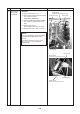
Drain pan