TEC Thermal Printer B-570 SERIES Maintenance Manual Document No. EM18-33010A Original Nov., 1993 (Revision Apr.
EM18-33010A (Revision Date Feb. 01 ’96) TABLE OF CONTENTS Page 1. UNPACKING ...................................................................................................... 1- 1 1.1 Procedures .................................................................................................. 1- 1 1.2 Checks ........................................................................................................ 1- 1 2. MAJOR UNIT REPLACEMENT ...........................................................
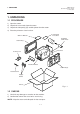
EM18-33010A (Revision Date Sep. 14 ’95) 1.1 Procedure 1. UNPACKING 1. UNPACKING 1.1 PROCEDURE 1) Open the carton. 2) Unpack the accessories from the carton. 3) Unpack the side pad (L)/(R) and the printer from the carton. 4) Place the printer on a level surface. Unpacking Procedure Owner’s Manual Rewinder Guide Plate Side Pad (L) Rear Pad Power Cord Thermal Printer Side Pad (R) Head Cleaner Supply Holder Carton Fig. 1-1 1.2 CHECKS 1) Check for any damage or scratches on the machine.
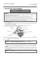
EM18-33010A (Revision Date Dec. 09, ’94) 2. MAJOR UNIT REPLACEMENT 2. MAJOR UNIT REPLACEMENT 2. MAJOR UNIT REPLACEMENT WARNING! Disconnect power cord before replacing important parts. CAUTION: 1. NEVER separate the ribbon motors from the attaching plate (bracket), because doing so will change their adjustment. (See Fig. 2-8) 2. NEVER remove the two screws painted red on the side of the print block. (See Fig. 2-13) 3. NEVER remove the four screws on the side of the print block. (See Fig. 2-13) 4.
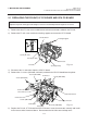
EM18-33010A (Revision Date Oct. 14, ’94) 2.1 REPLACING THE PS UNIT, I/F PC BOARD AND CPU PC BOARD 2. MAJOR UNIT REPLACEMENT 2.1 REPLACING THE PS UNIT, I/F PC BOARD AND CPU PC BOARD CAUTION: Replace only with same type and ratings of fuse for continued protection against risk of fire. 1) Remove the three FL-4x6 screws and disconnect the two connectors to detach the PS unit. 2) Remove the FL-3x5 screw and the four locking supports to remove the I/F PC board.
EM18-33010A 2. MAJOR UNIT REPLACEMENT 2.1 REPLACING THE PS UNIT, I/F PC BOARD AND CPU PC BOARD 6) Adjust the ribbon end sensor. Use the following Ribbons; TTM-78 (Maker: Fujicopian) 1 Set the ribbon so that the ribbon end sensor can detect the ribbon. Turn the power on. 2 Turn the VR2 so that the voltage between Pin 1 (GND) and Pin 7 of CN10 is 3.0 ± 0.2 V with an oscilloscope. 3 Turn the power off and mount the left side cover and top cover.
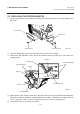
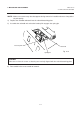
EM18-33010A 2. MAJOR UNIT REPLACEMENT 2.2 REPLACING THE STEPPING MOTOR 2.2 REPLACING THE STEPPING MOTOR 1) Remove the two black screws to detach the front plate, remove the two FL-4x6 screws to detach the belt cover. Front Plate Belt Cover Black Screw Screw (FL-4x6) Fig. 2-6 2) Unclamp and disconnect the connector from CN14 on the CPU PC board. 3) Remove the two SM-4x8B screws, loosen the two belts from the pinion gear, and remove the stepping motor.
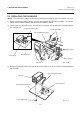
EM18-33010A 2. MAJOR UNIT REPLACEMENT 2.3 REPLACING THE RIBBON MORTORS 2.3 REPLACING THE RIBBON MOTORS CAUTION: NEVER separate the ribbon motors from the attaching plate because doing so will change their adjustment. 1) Disconnect the connector and remove the two SM-3x5B screws to detach the ribbon motors. FLOIL G-488 FLOIL Attaching Plate FLOIL G-488 Ribbon Motor Screw (SM-3x5B) Connector (Red) Connector (Black) Attaching Plate Dowels Ribbon Motor Fig.
EM18-33010A 2. MAJOR UNIT REPLACEMENT 2.5 REPLACING THE SOLENOID 2.5 REPLACING THE SOLENOID NOTE: The following procedure can be employed without removing the top cover and left side cover. 1) Before removing the ribbon stopper, check its attaching direction for later installation. Remove the ribbon stopper from the ribbon shaft on which the ribbon is wound. 2) Remove the two SM-4x8B screws, disconnect the connector CN1 on the RSV PC board to detach the solenoid unit.
EM18-33010A 2. MAJOR UNIT REPLACEMENT 2.5 REPLACING THE SOLENOID NOTE: Make sure to remove any dust that appears during removal or installation because it may affect the print quality. 4) Replace the solenoid and attach it to the solenoid attaching plate. 5) Assemble the solenoid unit so that the head up link engages the spring pin. Head Up Link Solenoid Fig. 2-12 Spring Pin CAUTION: Take care to orient the screws so that they are vertically aligned with the solenoid attaching plate.
EM18-33010A (Revision Date Feb. 01, ’96) 2.6 REPLACING THE PRINT HEAD 2. MAJOR UNIT REPLACEMENT 2.6 REPLACING THE PRINT HEAD CAUTION: 1. NEVER touch the element when handling the print head. 2. NEVER touch the connector pins to avoid a breakdown of the print head by static electricity. 3. NEVER remove the two screws painted red on the side of the print block. 4. NEVER remove the four screws on the side of the print block. 5.
EM18-33010A (Revision Date Feb. 01, ’96) 2.6 REPLACING THE PRINT HEAD 2. MAJOR UNIT REPLACEMENT ■ Adjusting the print head position 1 Fit the jig in the platen and strip shaft. 2 Press the jig at an angle of 45° until it is sung against the print head. Then secure the print head. Platen Print Head Jig Strip Shaft Ceramic Strip Shaft Platen Fig. 2-14 3 Remove the jig. 4 Refer to page 6-43 and clear the maintenance counter. 5 Refer to page 6-31 and perform test print.
EM18-33010A (Revision Date Feb. 01, ’96) 2.6 REPLACING THE PRINT HEAD 2. MAJOR UNIT REPLACEMENT 2.6.2 New type print head NOTE: NEVER loosen screws other than two SM-4x8B. 1) Turn the head lever clockwise to lower the print head. Remove the two SM-4x8B screws. 2) Turn the head lever counterclockwise and disconnect the two connectors to detach the print head from the print block. Screws (NEVER remove these screws.) Screw (SM-4x8B) Print Block Connector B Screws painted red (NEVER remove these screws.
EM18-33010A 2. MAJOR UNIT REPLACEMENT 2.6 REPLACING THE PRINT HEAD Print Head Bracket Print Head b (securing the print head) b c A (Print Head Position Adjusting Pin) c (securing the adjusting pin) Fig. 2-16 (1) Loosen the screws c securing the print head position adjusting pin. (2) Loosen the screws b one by one, slightly move the print head backward or forward, and then tighten the screws b and c . Ensure that the print head is parallel to the platen. If not, print tone will be uneven.
EM18-33010A (Revision Date Sep. 29, ‘95) 2.7 REPLACING THE PLATEN AND FEED ROLLER 2. MAJOR UNIT REPLACEMENT 3) Disconnect the connector for the strip sensor (LED). 4) Remove the six screws (FL-4x6, B-4x12 and P-3x12) to detach the right plate ass’y. Right Plate Screw (B-4x12) Screws painted red (NEVER remove these screws.) Connector Strip Sensor (LED) Screw (B-4x12) Screw (FL-4x6) Screw (P-3x12) Fig.
EM18-33010A 2. MAJOR UNIT REPLACEMENT 2.8 REPLACING THE PAPER SENSOR 2.8 REPLACING THE PAPER SENSOR NOTE: Turn the knob until the paper sensor reaches full forward. 1) Disconnent the connector for the strip sensor (LED) to remove right plate ass’y. (See Figs. 2-17 and 2-18.) 2) Disconnect the connectors for the paper sensor. 3) Remove M1.5 E-ring, M3 washer and paper sensor unit. 4) Remove M1.5 E-ring, turn the knob counter clockwise, then remove the paper sensor.
EM18-33010A (Revision Date Sep. 29, ’95) 2.10 REPLACING THE PINCH ROLLER SHAFT ASS’Y 2. MAJOR UNIT REPLACEMENT 2.10 REPLACING THE PINCH ROLLER SHAFT ASS’Y 1) Turn the head lever to position 3 , and release the ribbon shaft holder plate. 2) Remove the black screw to detach the media guide plate. Media Sensor B 1.5 mm~2.5 mm B Printer Block Base Media Guide Plate Black Screw (HAA-0004001) Fig. 2-22 3) Remove the SM-4x8B screw to detach the spring plate.
EM18-33010A (Revision Date Sep. 29, ’95) 2.10 REPLACING THE PINCH ROLLER SHAFT ASS’Y 2. MAJOR UNIT REPLACEMENT ■ Adjustment 1. Install the pinch roller unit so it parallels the base. If it does not, change the engaging position of the pinch roller belt and the pulley. Pinch Roller Belt Pinch Roller Unit Pulley Base Fig. 2-24 2. Attach the jig to the platen, feed roller and pinch roller shaft as shown in the figure below.
EM18-33010A (Revision Date Sep. 29, ’95) 2.10 REPLACING THE PINCH ROLLER SHAFT ASS’Y 2. MAJOR UNIT REPLACEMENT 3. Turn the head lever clockwise to lock the pinch roller shaft ass’y. Attach the spring plate to the pinch roller frame with the two SM-4x8B screws, pushing the spring plate toward the rear of the printer. SM-4x8B Spring Plate Pinch Roller Frame Pinch Roller Shaft Ass’y Fig.
EM18-33010A 3. INSTALLATION PROCEDURE FOR THE OPTIONAL EQUIPMENT 3.1 HIGH SPEED PC INTERFACE BOARD (B-4800-PC-QM) 3. INSTALLATION PROCEDURE FOR THE OPTIONAL EQUIPMENT WARNING! Make sure to unplug the power cord before installing the optional equipment. 3.1 HIGH SPEED PC INTERFACE BOARD (B-4800-PC-QM) The high speed PC interface board can be used together with the IBM PC-AT or its compatible machine only.
EM18-33010A 3. INSTALLATION PROCEDURE FOR THE OPTIONAL EQUIPMENT 3.1 HIGH SPEED PC INTERFACE BOARD (B-4800-PC-QM) 6. Connect the printer cable to the connector (CN1) on the BPE PC board. 7. Put the cable strain relief of the printer cable in the notch of the cable support plate. Secure the cable strain relief to the cable support plate by turning the nut. 8. Attach the cable support plate to the printer with the FL3x5 screws removed in step 2.
EM18-33010A 3. INSTALLATION PROCEDURE FOR THE OPTIONAL EQUIPMENT 3.2 CUTTER MODULE (B-4205-QM) 3.2 CUTTER MODULE (B-4205-QM) Description Q’ty/Unit Description Q’ty/Unit Cutter Unit 1 Cutter Attaching Screw 2 Cutter Cover 1 Screw (FL-4x6) 1 Take-up/Cutter Harness 1 Cleaner 1 NOTE: For the B-570 series, the take-up/cutter harness enclosed with the B-4205-QM is not used but the take-up harness connected to CN2 on the PWM PC board. 1. Remove the top cover and left side cover. (See Fig. 2-1.
EM18-33010A SVO7A1003: Nov. 21 ’97 3.2 CUTTER MODULE (B-4205-QM) 3. INSTALLATION PROCEDURE FOR THE OPTIONAL EQUIPMENT 7. Install the cutter unit with the attached screws (cutter attaching screw, FL-4x6). When installing the cutter, make sure that the cutter guide is not in contact with the platen. If it is, print failure or noise may be caused. Fig. 3-5 8. Remove the motor cover. (See Fig. 2-9.) 9. Disconnect the connector from CN2 on the PWM PC board.
EM18-33010A (Revision Date Aug. 11, ’95) 3.2 CUTTER MODULE (B-4205-QM) 3. INSTALLATION PROCEDURE FOR THE OPTIONAL EQUIPMENT 10. Mount the cutter cover with the two screws. Screw Cutter Attaching Screw Cutter Cover Fig. 3-7 11. Reassemble the motor cover, rewind full sensor (Tr), I/F PC board, left side cover and top cover in order. 12. After reassembly is complete, perform a test print to confirm that the cutter works properly. After printing a print sample at a speed of 8”/sec.
EM18-33010A 3. INSTALLATION PROCEDURE FOR THE OPTIONAL EQUIPMENT 3.3 MEMORY MODULE 3.3 MEMORY MODULE 1. Remove the top cover and left side cover. (See Fig. 2-1.) 2. Hold the memory module so that the Pin 1 is on the upper right, then attach the memory module to the IC socket. Expanding the memory must be performed in sequence, IC19, IC20, IC21, IC22, IC23 and IC24. CPU PC Board IC19 IC Socket IC24 Memory Module Fig. 3-9 Pin 1 3. Reassemble the left side cover in the reverse order of removal.
EM18-33010A (Revision Date Apr. 28, ’95) 3.4 FANFOLD PAPER GUIDE MODULE (B-4905-FF-QM) 3. INSTALLATION PROCEDURE FOR THE OPTIONAL EQUIPMENT 3.4 FANFOLD PAPER GUIDE MODULE (B-4905-FF-QM) Description Q’ty/Unit Fanfold Paper Guide(rear) 1 Fanfood Paper Guide (front) 1 1. Open the top cover. 2. Remove the T-4x8 screws to detach the paper guide ass’y at the center of the printer and attach the fanfold paper guide (front) with these same screws. Fanfold Paper Guide (front) Screw (T-4x8) Fig. 3-10 3.
EM18-33010A 4. MECHANISM DESCRIPTION 4.1 CUTTER DRIVE (CUTTER MODE) 4. MECHANISM DESCRIPTION 4.1 CUTTER DRIVE (CUTTER MODE) The printer supplies DC + 27 V to the cutter motor to rotate the cutter motor and clutch counter clockwise. The arm swings like a pendulum and moves the fixed slide cutter up and down to make a cut. Micro Switch Fixed Cutter Slide Cutter Slide Cutter Cutter Motor Cutter Motor Clutch Arm Fig.
EM18-33010A 4. MECHANISM DESCRIPTION 4.2 HARNESS WIRING 4.2 HARNESS WIRING TH Sensor Cutter Harness Take-up Harness Sensor Harness Solenoid Harness Rewind Full Sensor Strip Sensor Clamp DC Motor Harness Clamp Cable Band (Do not bind the strip sensor, stepping motor and Solenoid Harness) Clamp HS Harness LCD Harness I/F PC Board Ass’y Cable Band CPU PC Board Ass’y LCD Harness LED Harness LED Harness Clamp HP Harness Stepping Motor Inlet Ass’y PS Unit 4-2 PS Harness Fig.
EM18-33010A 5. TROUBLESHOOTING 5. TROUBLESHOOTING 5. TROUBLESHOOTING Problems Cause Solution Power is not turned ON. 1. Input voltage to the printer is not within the rated voltage. (Check by CN1 on the PS unit.) 2. Output voltage from the printer is not within the rated voltage. (Check that the voltage between Pin 4 and Pin 6 (GND) of CN2 on the PS unit is 27 V. And check the voltage between Pin 1 and Pin 3 (GND) is 5 V.) 3. CPU PC board is not applied with voltage.
EM18-33010A 5. TROUBLESHOOTING 5. TROUBLESHOOTING Problems Cause Solution Dot missing 1. Broken element of print head 2. Broken wires of print head cable 3. Failure of the CPU PC board • Replace the print head. • Replace the print head harness. • Replace the CPU PC board. Blurred print 1. Poor quality of media. • Use only TOSHIBA TEC specified media. • Clean the print head and remove the dust from the media. 2. Dust is attached to the media. Ribbon wrinkle 1. Poor quality of the ribbon 2.
EM18-33010A (Revision Date: Dec. 10 '99) TABLE OF CONTENTS Page 6. DIAG. TEST OPERATION .................................................................................. 6- 1 6.1 OUTLINE OF THE DIAG. TEST OPERATION ........................................... 6- 1 6.2 SELF TEST MODE ..................................................................................... 6- 3 6.2.1 Maintenance Counter Printing .......................................................... 6- 3 6.2.
EM18-33010A (Revision Date: Dec. 10 ‘99) 6.1 OUTLINE OF THE DIAG. TEST OPERATION 6. DIAG. TEST OPERATION 6. DIAG. TEST OPERATION 6.1 OUTLINE OF THE DIAG. TEST OPERATION In system mode the diag. test operation is used to diagnose the printer and to set the parameters by using the [FEED], [RESTART] and [PAUSE] keys on the operation panel. Diag. test operation (Type I) is started from the power off state and the parameter setting (Type II) is started while the printer is on-line or printing.
EM18-33010A (Revision Date Sep. 27, ’95) 6.1 OUTLINE OF THE DIAG. TEST OPERATION 6. DIAG. TEST OPERATION ■ Type II The parameter setting such as feed length fine adjustment or cut/strip position fine adjustment can be changed while the printer is on-line or printing. Pressing the [PAUSE] key causes the printer to enter parameter setting mode. Reset mode is provided for this procedure to cancel the steps which follow the [PAUSE] key without turning the power off.
EM18-33010A (Revision Date Jan. 14, ’99) 6.2 SELF TEST MODE 6. DIAG. TEST OPERATION 6.2 SELF TEST MODE In self test mode the printer status is printed in two types of sample print. The result of the head broken element check is indicated in the display. 6.2.1 Maintenance Counter Printing The data from 1 to 31 on a sample print is printed. This data is the printer status and the value set in the parameter setting mode. Power off Turn on the power while holding down the [FEED] key and [PAUSE] key.
EM18-33010A (Revision Date: Dec. 10 ‘99) 6.2 SELF TEST MODE 6. DIAG. TEST OPERATION ■ Sample Print [Print Condition] • Preset count • Print speed • Sensor • Printing method • Supply length • Issuing mode (1) (2) :1 : 127 mm/sec.
EM18-33010A (Revision Date: Dec. 10 ‘99) 6.2 SELF TEST MODE 6. DIAG. TEST OPERATION 2) Parameters # Contents Item PC-850 PC-8 : PC-850 : PC-8 0 Ø : No slash used. : Slash used. (12) Control code selection AUTO ESC LF NUL { } 1B 1C 1D : : : : (13) Ribbon type selection TRANS. NON TRANS. : Transmissive ribbon : Non-transmissive ribbon (14) Feed length fine adjustment (19) (PC), (KEY) -50.0 mm to +50.0 mm (15) Cut/strip position fine adjustment (20) (PC), (KEY) -50.0 mm to +50.
EM18-33010A (Revision Date Jan. 13, ’95) 6.2 SLEF TEST MODE 6. DIAG. TEST OPERATION 6.2.2 Automatic Diagnostic Printing The data from 1 to 9 on a sample print is printed. Power off Turn on the power while holding down the [FEED] key and [PAUSE] key. < 1> D I AG NO ST I C V1 . 0 A Press the [PAUSE] key. R IB B O N T RA N SM I SS I V E Select the ribbon type from those at the right by pressing the [FEED] key or [RESTART] key. Press the [PAUSE] key. Continued on Section 6.2.
EM18-33010A 6. DIAG. TEST OPERATION 6.2 SELF TEST MODE ■ Sample Print [Print Condition] • Preset count • Print speed • Sensor • Printing method • Supply length • Issuing mode 1 : : : : : : 2 1 127 mm/sec. No sensor Thermal transfer 50 mm Batch printing (without rewinder) PROGRAM MASK KANJI 7 EEPROM DRAM CARD SENSOR1 SENSOR2 8 9 DIP SW EXP.I/O 3 4 5 6 V1.0A FMRM0034801:2800 V1.0 FMRM0034901:B100 0000:0000 0000:0000:0000:0000 OK 1024KB OK 00000000,10110011 [H]3.1V [A]2.8V [R]3.3V [T]2.
EM18-33010A 6. DIAG. TEST OPERATION 6.2 SELF TEST MODE 3 EEPROM Check EEPROM OK Read/write check OK: Data in the check area can be properly read/written. NG: Data in the check area cannot be properly read/written. EEPROM: Backup memory 4 DRAM Check DRAM 1024KB Readable/writable area DRAM: Image buffer memory or work memory NOTE: If an error is detected during DRAM check, the display od readable/writable area will stop when the error occurs.
EM18-33010A 6. DIAG. TEST OPERATION 6.2 SELF TEST MODE 6 Sensor 1 Check SENSOR1 0 0 0 0 0 0 0 0 , 1 0 1 1 0 0 1 1 Head up switch status 0: Head opened 1: Head closed Fixed to 1 Cutter home position switch status 0: Home position 1: Other position Rewind full sensor status 0: Normal 1: Excess Slit sensor #1 (ribbon rewind) status 0: The detecting point is positioned outside the slit. 1: The detecting point is positioned inside the slit.
EM18-33010A 6. DIAG. TEST OPERATION 6.2 SELF TEST MODE ■ Print status content description of each sensor/switch Sensor/Switch Print status content description Head up switch Indicates whether the print head is opened or closed. Cutter home position switch Indicates whether the cutter is at the home position or not. Rewind full sensor Indicates whether the media is wound to peak capacity on the builtin take-up spool or not.
EM18-33010A (Revision Date Jan. 13, ’95) 6.2 SELF TEST MODE 6. DIAG. TEST OPERATION 8 DIP SW Check 8 7 6 5 4 3 2 1 0 0 0 0 0 0 0 0 DIP SW 8 7 6 5 4 3 2 1 1 0 0 0 1 0 1 0 Pin No. Status DIP Switch 2 0: OFF (OPEN) 1: ON (SHORT) DIP Switch 1 0: OFF (OPEN) 1: ON (SHORT) NOTE: The DIP switch 1-7 is to be set to 0 (OFF:OPEN) regardless of setting item. 9 EXP. I/O Check EXP. I/O OK Loopback test OK: The circuit has no problem. NG: The circuit has a problem or loopback jig is not attached.
EM18-33010A (Revision Date Jul. 03, ’97) 6.2 SELF TEST MODE 6. DIAG. TEST OPERATION 6.2.3 Head Broken Element Check The printer automatically performs the head broken element check. The result of the head broken element check is indicated in the display. Power off Turn on the power while holding down the [FEED] key and [PAUSE] key. < 1> D I AG NO STI C V1. 0A Press the [PAUSE] key twice. Press the [FEED] key twice. T HE R M AL H EAD C HECK Press the [PAUSE] key.
EM18-33010A (Revision Date: Dec. 10 ‘99) 6.3 PARAMETER SETTING MODE 6. DIAG. TEST OPERATION 6.3 PARAMETER SETTING MODE The following items are set in the parameter setting mode. The values set in this mode are printed on the sample print of the maintenance counter. Setting procedure and functions are provided below. Power off Press the [PAUSE] key. Turn on the power while holding down the [FEED] key and [PAUSE] key. < 1> DI AG NO STI C Z ER O FO NT 0 Press the [PAUSE] key. V1.
EM18-33010A (Revision Date: Dec. 10 ‘99) 6.3 PARAMETER SETTING MODE 6. DIAG. TEST OPERATION ■ Parameter Setting Mode Table Mode Name Function FEED ADJUST Using this parameter the feed length is fine adjusted. CUT ADJUST Using this parameter the cut position or strip position is fine adjusted. BACK FEED ADJ. Using this parameter the back feed length from the cut/strip position to the home position is fine adjusted. X ADJUST This setting is used to finely adjust print position in the X axis.
EM18-33010A 6. DIAG. TEST OPERATION 6.3 PARAMETER SETTING MODE 6.3.1 Feed Length Fine Adjustment Power off Turn on the power while holding down the [FEED] key and [PAUSE] key. < 1> D I AG NO ST I C V1 . 0 A Press the [FEED] key. < 2> P A RA ME TE R S E T Press the [PAUSE] key. F EE D AD JU ST + 0. 0 m m ■ [FEED] key: Press the [FEED] or [RESTART] key to adjust the feed length. (See NOTE 1.) Press the [FEED] key and [RESTART] key at the same time. Pressing the [FEED] key one time is a -0.
EM18-33010A (Revision Date Jan. 13, ’95) 6.3 PARAMETER SETTING MODE 6. DIAG. TEST OPERATION 6.3.2 Cut/Strip Position Fine Adjustment Power off Turn on the power while holding down the [FEED] key and [PAUSE] key. < 1> D I AG NO ST I C V1 . 0 A Press the [FEED] key. < 2> P A RA ME TE R S E T Press the [PAUSE] key twice. C UT A DJ US T + 0. 0 m m ■ [FEED] key: Press the [FEED] or [RESTART] key to adjust the feed length. (See NOTE 1.) Press the [FEED] key and [RESTART] key at the same time.
EM18-33010A 6. DIAG. TEST OPERATION 6.3 PARAMETER SETTING MODE 6.3.3 Back Feed Length Fine Adjustment Power off Turn on the power while hoding down the [FEED] key and [PAUSE] key. < 1> D I AG NO ST I C V1 . 0 A Press the [FEED] key. < 2> P A RA ME TE R S E T Press the [PAUSE] key three times. B AC K FE ED A D J. + 0. 0 m m Press the [FEED] or [RESTART] key to adjust the feed length. (See NOTE 1.) ■ [FEED] key: Press the [FEED] key and [RESTART] key at the same time. Press the [PAUSE] key.
EM18-33010A 6. DIAG. TEST OPERATION 6.3 PARAMETER SETTING MODE + 0.0 mm Feed Direction A A A A ■ Feed Length Fine Adjustment Example Fig. 6-4 - 10.0 mm A A A A - 10 mm Fig. 6-5 + 10.0 mm A A A A + 10 mm Fig. 6-6 ■ Cut Position Fine Adjustment Example Cut Position + 0.0 mm Print Head Tag Paper Feed Direction Black Mark - 12.0 mm Platen Fig. 6-7 - 12 mm Fig. 6-8 + 12.0 mm + 12 mm Fig.
EM18-33010A (Revision Date Aug. 25, ’95) 6.3 PARAMETER SETTING MODE 6. DIAG. TEST OPERATION ■ When using a label with a length of less than 38 mm : Case 1 Condition: Issue command [ESC]XS, feed command [ESC]T and eject command [ESC]IB are received. Label pitch: 38.0 mm or less, with cut, feed gap sensor, cut position fine adjustment value ± 10 mm or less, and issue mode set to C (cut).
EM18-33010A (Revision Date Jul. 28, ’94) 6.3 PARAMETER SETTING MODE 6. DIAG. TEST OPERATION ■ Strip Position Fine Adjustment Example Print Head Label + 0.0 mm Platen Fig. 6-11 Strip Shaft Backing Paper Print Head + 3.0 mm + 3.0 mm Platen Fig. 6-12 Strip Shaft Backing Paper Print Head - 3.0 mm - 3.0 mm Platen Fig.
EM18-33010A 6. DIAG. TEST OPERATION 6.3 PARAMETER SETTING MODE + 0.0 mm Feed Direction A A A A ■ Back Feed Length Fine Adjustment Example Fig. 6-15 Print start position -3.0 mm Fig. 6-16 -3.0 mm A A A A +3.0 mm A A A A +3.0 mm 6-21 Fig.
EM18-33010A 6. DIAG. TEST OPERATION 6.3 PARAMETER SETTING MODE 6.3.4 X Axis Fine Adjustment Power off Turn on the power while holding down the [FEED] key and [PAUSE] key. < 1> DI AG NO STI C V1 . 0 A Press the [FEED] key. < 2> PA RA ME TER S E T Press the [PAUSE] key four times. X A D J US T +0.0 mm ■ [FEED] key: Pressing the [FEED] key one time is a -0.5 mm change, up to -99.5 mm. (See NOTE 2.) ■ [RESTART] key: Pressing the [RESTART] key one time is a +0.5 mm change, up to +99.5 mm.
EM18-33010A 6. DIAG. TEST OPERATION 6.3 PARAMETER SETTING MODE ■ X Axis Fine Adjustment Example Feed direction Top first printing X Y ABC + 0.0 mm Y Fig. 6-18 X Bottom first printing -50.0 mm -50.0 mm ABC Fig. 6-19 + 50.0 mm +50.0 mm ABC Fig. 6-20 NOTES: 1. The X axis fine adjustment is performed to fine adjust the X axis of the drawing in the left or right direction. 2. Adjust the X axis in the effective print range.
EM18-33010A (Revision Date: Jan. 14 ‘99) 6.3 PARAMETER SETTING MODE 6. DIAG. TEST OPERATION 6.3.5 Print Tone Fine Adjustment Power off Turn on the power while holding down the [FEED] key and [PAUSE] key. < 1> D I AG NO ST I C V1 . 0 A Press the [FEED] key. < 2> P A RA ME TE R S E T Press the [PAUSE] key five times. T ON E AD JU ST + 0 ■ [FEED] key: Press the [FEED] or [RESTART] key to adjust the feed length. (See NOTE 1.
EM18-33010A 6. DIAG. TEST OPERATION 6.3 PARAMETER SETTING MODE 6.3.6 Character Code Selection Power off Turn on the power while holding down the [FEED] key and [PAUSE] key. < 1> DI AG NO STI C V1. OA Press the [FEED] key. < 2> PA RA ME TER S ET Press the [PAUSE] key seven times. F ON T CO DE PC-8 50 • PC-850 • PC-8 Select either character code with the [FEED] key or [RESTART] key. (See NOTE 1.) Press the [FEED] key and [RESTART] key at the same time. Press the [PAUSE] key.
EM18-33010A 6. DIAG. TEST OPERATION 6.3 PARAMETER SETTING MODE 6.3.7 Font Zero Selection Power off Turn on the power while holding down the [FEED] key and [PAUSE] key. < 1> D I AG NO ST I C V1. OA Press the [FEED] key. < 2> P A RA ME TE R S ET Press the [PAUSE] key eight times. Z E RO FO NT 0 • 0 (without slash) • ø (with slash) Select either zero font with the [FEED] key or [RESTART] key. (See NOTE 1.) Press the [FEED] key and [RESTART] key at the same time. Press the [PAUSE] key.
EM18-33010A SVO8A1002 : Jan. 19, '98 6.3 PARAMETER SETTING MODE 6. DIAG. TEST OPERATION 6.3.8 Control Code Selection Power off Turn on the power while holding down the [FEED] key and [PAUSE] key. < 1 >DI AG NO STI C V1. OA Press the [FEED] key. < 2 >PA RA ME TER S ET Press the [PAUSE] key nine times. C O DE AU TO Select control code with the [FEED] key or [RESTART] key. (See NOTE 1.) When {MANUAL} is selected, go to A on the next page. B Press the [FEED] key and [RESTART] key at the same time.
EM18-33010A SVO8A1002 : Jan. 19, '98 6.3 PARAMETER SETTING MODE 6. DIAG. TEST OPERATION A C OD E M AN U A L Change the control code. Press the [PAUSE] key. C ON T L OL C OD E 1 1 B Set the control code 1. (equivalent to ESC, {.) 1 C Set the control code 2. (equivalent to LF, .) 1 D Set the control code 3. (equivalent to NUL, }.) Press the [PAUSE] key. C ON T R OL C OD E 2 Press the [PAUSE] key. C ON T R OL C OD E 3 Go to B on the previous page.
EM18-33010A (Revision Date Jun. 28, ’96) 6.3 PARAMETER SETTING MODE 6. DIAG. TEST OPERATION 6.3.9 Ribbon Type Selection Power off Turn on the power while holding down the [FEED] key and [PAUSE] key. < 1> D I AG NO ST I C V1 . O A Press the [FEED] key. < 2> P A RA ME TE R S E T Press the [PAUSE] key ten times. R I BB O N T RA N S .
EM18-33010A (Revision Date Jun. 28, ’96) 6.3 PARAMETER SETTING MODE 6. DIAG. TEST OPERATION 6.3.10 Ribbon Motor Drive Voltage Fine Adjustment Power off Turn on the power while holding down the [FEED] key and [PAUSE] key. < 1> DI AG NO STI C V1. OA Press the [FEED] key. < 2> PA RA ME TER S ET Press the [PAUSE] key eleven times. R I BBO N AD J < FW D > Press the [FEED] or [RESTART] key to fine adjust the feed motor voltage. (See NOTE 1.) Press the [PAUSE] key. (See NOTE 3.
EM18-33010A (Revision Date Dec. 10, ’96) 6.3 PARAMETER SETTING MODE 6. DIAG. TEST OPERATION 6.3.11 Strip Wait Status Setting Power off Turn on the power while holding down the [FEED] key and [PAUSE] key. < 1> D I AG NO ST I C V1 . O A Press the [FEED] key. < 2> P A RA ME TE R S E T Press the [PAUSE] key thirteen times. S T AT U S TY PE 1 Press the [FEED] key or [RESTART] key to select the strip wait status. ■ [FEED] key: Status type 2: A strip wait status is sent.
EM18-33010A SVO8A1002 : Jan. 19, '98 6.3 PARAMETER SETTING MODE 6. DIAG. TEST OPERATION 6.3.12 Stacker Selection Power off Turn on the power while holding down the [FEED] key and [PAUSE] key. < 1> D I AG NO ST I C V1. OA Press the [PAUSE] key. < 2> P A RA ME TE R S ET Press the [PAUSE] key fourteen times. S T AC K ER S YS T EM O FF ■ [FEED] key: ON: Stacker is used. ■ [RESTART] key: Press the [FEED] key or [RESTART] key to select ON or OFF to the stacker. OFF: Stacker is not used.
EM18-33010A (Revision Date: Dec. 10 ‘99) 6.3 PARAMETER SETTING MODE 6. DIAG. TEST OPERATION 6.3.13 Threshold Manual Fine Adjustment for the Black Mark Sensor Power off Turn on the power while holding down the [FEED] key and [PAUSE] key. < 1> D I AG NO ST I C V1 . O A Press the [PAUSE] key. < 2> P A RA ME TE R S E T Press the [PAUSE] key fifteen times. T H RE S HO LD R 1 . 0 V Press the [FEED] key or [RESTART] key to fine adjust the black mark sensor manual threshold.
EM18-33010A (Revision Date: Dec. 10 ‘99) 6.3 PARAMETER SETTING MODE 6. DIAG. TEST OPERATION 6.3.14 Threshold Manual Fine Adjustment for the Feed Gap Sensor Power off Turn on the power while holding down the [FEED] key and [PAUSE] key. < 1> D I AG NO ST I C V1 . O A Press the [PAUSE] key. < 2> P A RA ME TE R S E T Press the [PAUSE] key sixteen times. T H RE S HO LD T 1 . 4 V Press the [FEED] key or [RESTART] key to fine adjust the feed gap sensor manual threshold.
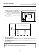
EM18-33010A (Revision Date: Jan. 14 ‘99) 6.3 PARAMETER SETTING MODE 6. DIAG. TEST OPERATION ■ How To Calculate Theshold Fine Adjustment Value If the following cases occurred, threshold value for the paper sensors should be fine adjusted after referring to the next page. Case 1: When using tag paper, the black mark and the print area are distinguished from each other by the 1.5V or more difference of sensor output voltage. If a low-sensitive sensor is installed in the printer, it may not detect 1.
EM18-33010A (Revision Date: Jan. 14 ‘99) 6.3 PARAMETER SETTING MODE 6. DIAG. TEST OPERATION NOTE: The following operation cannot be performed unless the sensor type is changed by the issue command or feed command. (1) Using the sensor adjustment in Diag. mode, measure the sensor voltage at the following four points. Label: Print area Backing paper Tag paper: Print area Black mark Example: [REFLECTIVE] 2.8V [TRANSMISSIVE] 4.
EM18-33010A (Revision Date: Jan. 14 ‘99) 6.3 PARAMETER SETTING MODE 6. DIAG. TEST OPERATION 6.3.15 Kanji Code Selection Power off Turn on the power while holding down the [FEED] key and [PAUSE] key. < 1> D I AG NO STI C V1. OA Press the [PAUSE] key. < 2> P A RA ME TER S ET Press the [PAUSE] key 17 times. K A NJ I C OD E TYP E1 Select either code with the [FEED] key or [RESTART] key. Press the [FEED] key and [RESTART] key at the same time. ■ Windows code ■ Original code Press the [PAUSE] key.
EM18-33010A (Revision Date: Aug. 5 ‘99) 6.3 PARAMETER SETTING MODE 6. DIAG. TEST OPERATION 6.3.16 Euro Font Code Selection Power off Turn on the power while holding down the [FEED] key and [PAUSE] key. < 1> D I AG NO ST I C V1 . O A Press the [PAUSE] key. < 2> P A RA ME TE R S E T Press the [PAUSE] key 18 times. E U RO C OD E B O H Select the Euro font code with the [FEED] key or [RESTART] key. •20H [RESTART] key ↑↓ [FEED] key •FFH Press the [PAUSE] key. Continued on Section 6.3.
EM18-33010A (Revision Date: Dec. 10 ‘99) 6.3 PARAMETER SETTING MODE 6. DIAG. TEST OPERATION 6.3.17 Transmission Control Mode Selection Power off Turn on the power while holding down the [FEED] key and [PAUSE] key. V 1 . OA < 1 > D I A GNOS T I C . Press the [FEED] key. < 2 > P A R A ME T E R SET Press the [PAUSE] key 19 times. DTR DTR/ RTS Select the Transmission Control Mode with the [FEED] key or [RESTART] key. Press the [FEED] key and [RESTART] key at the same time.
EM18-33010A (Revision Date: Dec. 10 ‘99) 6.3 PARAMETER SETTING MODE 6. DIAG. TEST OPERATION 6.3.18 Reset Selection when the INPUT • PRIME Signal is ON. Reset ON/OFF when the INPUT • PRIME signal ON is selected. Power off Turn on the power while holding down the [FEED] key and [PAUSE] key. < 1> DI AG NOS T IC. V 1. OA Press the [FEED] key. < 2> PA RA MET E R S ET Press the [PAUSE] key 20 times. I NP UT P RIM E ON Select the "Reset ON/OFF • ON: The printer will restore to the initial status.
EM18-33010A (Revision Date Feb. 07, ’97) 6.4 TEST PRINT MODE 6. DIAG. TEST OPERATION 6.4 TEST PRINT MODE Test print mode contains normal test print and process test print. 6.4.1 Normal Test Print Five kinds of test prints are provided in the test print mode. When performing the test print, 7 parameters should be set. The default parameter at power on is as below: • ISSUE COUNT : 1 • PRINT SPEED : 5 inch/sec.
EM18-33010A 6. DIAG. TEST OPERATION 6.4 TEST PRINT MODE From B of the preceding page. Set the print count from those at the right by pressing the [FEED] key or [RESTART] key. (See NOTE 2.) Press the [PAUSE] key. (See NOTE 3.) Set the print speed P RINT S PE ED 5000 1000 500 100 50 10 5 3 1 (Print count 5000) (Print count 1000) (Print count 500) (Print count 100) (Print count 50) (Print count 10) (Print count 5) (Print count 3) (Print count 1) To C of the preceding page.
EM18-33010A 6. DIAG. TEST OPERATION 6.4 TEST PRINT MODE From B of the preceding page. Set the issue mode type T YPE [ S] NO C UTTI NG Select the issue mode type from those at the right by pressing the [FEED] key or [RESTART] key. (See NOTE 2.) Press [PAUSE] key. (See NOTE 3.) [S] Standard mode (Batch printing without cut) [C] Auto-cut mode (Issue and cutting) [H] Strip mode (On-demand printing without cut) Press the [FEED] key and [RESTART] key at the same time. To C of the preceding page.
EM18-33010A (Revision Date Feb. 07, ’97) 6.4 TEST PRINT MODE 6. DIAG. TEST OPERATION From B of the preceding page. < 3>TE ST P RIN T Press the [PAUSE] key. P RINT C ON DIT IO N From A of the preceding page. Select the test print from those at the right by pressing the [FEED] key or [RESTART] key. A designated number of test prints are issued when pressing the [PAUSE] key. (See NOTE 8.
EM18-33010A (Revision Date Feb. 07, ’97) 6.4 TEST PRINT MODE 6. DIAG. TEST OPERATION 9. When the transmissive ribbon is selected and DIP SW. 1-1 is set to ON, and the space area is also 20 mm or more, the printer automatically enters ribbon saving print mode. 10. When “AUTO PRINT” is selected, 5 pcs. of the 3-dot slant line labels, bar code labels and character labels are printed respectively after one label is fed. ■ Test Print Sample • Slant line (1 dot) • Slant line (3 dot) Fig.
EM18-33010A (Revision Date Jan. 13, ’95) 6.4 TEST PRINT MODE 6. DIAG. TEST OPERATION 6.4.2 Process Test Print In the process test print, the test print is automatically performed on the following conditions. Parameter setting and print tone fine adjustment value is ignored. • OPERATION • ISSUE COUNT • PRINT SPEED • SENSOR : : : : One label feed, 3-dot slant line print, bar code print, character print 5 labels each 8 inches/sec.
EM18-33010A (Revision Date Jan. 13, ’95) 6.4 TEST PRINT MODE 6. DIAG. TEST OPERATION From B of the next page. A U TO PR IN T( R EF L EC T .) Press the [PAUSE] key. [Characters are printed on 5 labels.] < 3 >T E ST P RI N T Press the [PAUSE] key. From A of the preceding page. A U TO PR IN T( T RA N S. ) Press the [PAUSE] key. After feeding one label, slant lines (3 dots) are printed on 5 labels. A U TO Press the [FEED] key and [RESTART] key at the same time. To C of the preceding page.
EM18-33010A (Revision Date Jul. 08, ’94) 6.5 SENSOR SETTING MODE 6. DIAG. TEST OPERATION 6.5 SENSOR SETTING MODE Thermistor check and black mark/feed gap sensor settings are provided in the sensor setting mode. The value set in this mode is printed as data of sensor 2 in Automatic diagnosis printing in self test mode. 6.5.1 Thermistor Check Thermistor check should be performed to check the environmental temperature and print head temperature after the excess head temp.
EM18-33010A (Revision Date Jul. 08, ’94) 6.5 SENSOR SETTING MODE 6. DIAG. TEST OPERATION 6.5.2 Black Mark Sensor Adjustment Black mark sensor setting should be performed after replacing the CPU PC board or changing the tag paper to other maker’s one, or when a paper feed error occurs. Power off Turn on the power while holding down the [FEED] key and [PAUSE] key. < 1> D I AG NO ST I C V1 . O A Press the [FEED] key three times. < 4> S E NS OR Press the [FEED] key and [RESTART] key at the same time.
EM18-33010A (Revision Date: Jan. 14, ’98) 6.5 SENSOR SETTING MODE 6. DIAG. TEST OPERATION 6.5.3 Feed Gap Sensor Adjustment Feed gap sensor setting should be performed after replacing the CPU PC board or changing the label to other maker’s one, or when a paper feed error occurs. Power off Turn on the power while holding down the [FEED] key and [PAUSE] key. < 1> D I AG NO STI C V1. OA Press the [FEED] key three times. < 4> S E NS OR Press the [FEED] key and [RESTART] key at the same time.
EM18-33010A (Revision Date: Jan. 14 ’99) 6.5 SENSOR SETTING MODE 6. DIAG. TEST OPERATION 6.5.4 Paper End Setting for Black Mark Sensor Paper end setting should be performed after replacing the CPU PC board or changing the tag paper to other maker’s one, or when a paper feed error occurs. Power off Turn on the power while holding down the [FEED] key and [PAUSE] key. < 1> D I AG NO STI C V1. OA Press the [FEED] key three times. < 4> S E NS OR AD JU STME NT Press the [PAUSE] key four times.
EM18-33010A (Revision Date: Jan. 14 ’99) 6.5 SENSOR SETTING MODE 6. DIAG. TEST OPERATION 6.5.5 Paper End Setting for Feed Gap Sensor Paper end setting should be performed after replacing the CPU PC board or changing the label to other maker’s one, or when a paper feed error occurs. Power off Turn on the power while holding down the [FEED] key and [PAUSE] key. < 1> D I AG NO STI C V1. OA Press the [FEED] key three times. < 4> S E NS OR AD JU STME NT Press the [PAUSE] key five times. [ P E L EV EL .
EM18-33010A 6. DIAG. TEST OPERATION 6.6 RAM CLEAR MODE 6.6 RAM CLEAR MODE In RAM clear mode, various data written on the EEP-ROM can be initialized. There are two clear functions; Maintenance counter clear and parameter clear in the parameter setting mode. After referring to the following table specify and clear or initialize the data.
EM18-33010A (Revision Date: Dec. 10 ‘99) 6.6 RAM CLEAR MODE 6. DIAG.
EM18-33010A 6. DIAG. TEST OPERATION 6.6. RAM CLEAR MODE 6.6.1 Maintenance Counter Clear Power off Turn on the power while holding down the [FEED] key and [PAUSE] key. < 1> D I AG NO ST I C V1 . O A Press the [FEED] key four times. < 5> R A M CL EA R Press the [PAUSE] key. Press the [PAUSE] key. N O R A M CL EA R Press the [FEED] key. (or press the [RESTART] key twice.) Press the [FEED] key and [RESTART] key at the same time. M AI N T E CO UN T ER CL E A R Press the [PAUSE] key.
EM18-33010A 6. DIAG. TEST OPERATION 6.6 RAM CLEAR MODE 6.6.2 Parameter Clear Power off Turn on the power while holding down the [FEED] key and [PAUSE] key. < 1> DI AG NO STI C V1. OA Press the [FEED] key four times. < 5> RA M CL EAR Press the [PAUSE] key. Press the [PAUSE] key. N O RA M CL EAR Press the [FEED] key twice. (or press the [RESTART] key.) Press the [FEED] key and [RESTART] key at the same time. P AR AM ET ER CL EA R Press the [PAUSE] key. C OM PL ET E Turn off the power (See NOTE.
EM18-33010A 7. PROGRAM DOWN LOAD 7.1 FLOPPY DISK 7. PROGRAM DOWN LOAD The main program for the printer has been written onto the flash ROM. If the main program is upgraded, due to the addition/change of the specification, down load the main program from the PC to the printer with the down-load floppy disk and RS-232C interface or high speed PC interface. 7.1 FLOPPY DISK (1) Media .................... 3.5 inches (2DD) (2) System disk ..........
EM18-33010A (Revision Date Sep. 27, ’95) 7.3 DOWN LOAD PROCEDURE 7. PROGRAM DOWN LOAD 7.3 DOWN LOAD PROCEDURE (1) Turn the PC power on. (2) Turn the printer power on. (3) Inset the program down load floppy disk into the PC. (4) Change the drive to A. Type A : ↵ (5) Start the batch file “PDL”. Type P D L ↵ Or copy the contents of the floppy disk in to the hard disk and start the program in the hard disk. (6) After starting the batch file “PDL”, the following menu is displayed.
EM18-33010A 7. PROGRAM DOWN LOAD 7.3 DOWN LOAD PROCEDURE (11) When an error occurs, the following message is displayed together with the error code in line B . The following error occurred during transmission. (ERROR=##) Press any key to retry. Error code Doing so will revert to the displayed described in step (6). Refer to the error code to find the cause of the error. then retry the down load. (12) After terminating the down load, refer to the Maintenance Manual Section 6.