TOSHIBA Thermal Printer B-EV4 SERIES Printer Manual Document No. EO18-33025 Original (Revised Nov, 2008 ) This manual includes the contents of the Product Description, and Maintenance Manual.
EO18-33025 (Revision Date: Mar. 27, 2009) TABLE OF CONTENTS Page 1. OUTLINE------------------------------------------------------------------------------------------------------------- 1- 1 1.1 Features of the B-EV4D/EV4T-------------------------------------------------------------------------- 1- 1 1.1.1 Front View ------------------------------------------------------------------------------------------ 1- 1 1.1.
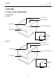
1. OUTLINE EO18-33025 1.1 Feature of the B-EV4D/EV4T 1. OUTLINE 1.1 Feature of the B-EV4D/EV4T 1.1.
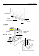
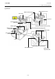
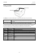
1. OUTLINE EO18-33025 1.1 Feature of the B-EV4D/EV4T 1.1.2 Rear View Fanfold paper slot Ethernet interface USB Interface Connector Power Switch Parallel Interface Connector (Centronics) Power Jack Serial Interface Connector (RS-232C) 1.1.
1. OUTLINE EO18-33025 1.
1. OUTLINE EO18-33025 1.2 Indication of the Model Name 1.2 Indication of the Model Name B - E V 4 D - G S 14 - QM - R RoHS compliance model Destination country/Region code QM: Standard for World Wide Interface 14: USB, Serial, Parallel and Ethernet Issue mode S: Standard Dot density of the print haed.
1. OUTLINE EO18-33025 1.3 Basic Specifications 1.
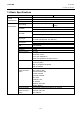
1. OUTLINE EO18-33025 (Revision Date: Mar. 27, 2009) 1.3 Basic Specifications Model Printer characteristics Media characteristics LED Key B-EV4D B-EV4T Bitmap: Alpha-numeric 20 types + Kanji 4 types Outline: 2 types Writable characters, Optional TTF One LED w/ 3 colors (w/ silk screen print of “STATUS”) Feed key (w/ silk screen print of “ FEED”) Switch Power S/W Label width 1” (25.4 mm) to 4.41” (112 mm) 203 dpi: 0.6” (15 mm) to 39” (999 mm) 300 dpi: 0.
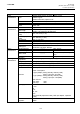
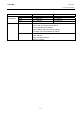
1. OUTLINE EO18-33025 1.3 Basic Specifications Model Width Physical characteristics Height Depth Weight Related products Options Accessories B-EV4D B-EV4T 7.8” (198 mm) 7.8” (198 mm) 6.7” (169.5 mm) 6.8” (173 mm) 10.2” (258 mm) 10.2” (258 mm) 2.5Kg or less 2.
1. OUTLINE EO18-33025 1.4 Key and LED 1.4 Key and LED STATUS Lamp FEED Button The [FEED] button operates as FEED button or PAUSE button depending on the printer statuses. As the FEED button As the PAUSE button Pressing this button when the printer is in online state causes a media feed. Pressing this button after removing a cause of an error returns the printer to online state. Pressing this button during printing stops printing after completing the current label.
1. OUTLINE EO18-33025 1.5 Supply Specifications 1.5 Supply Specifications 1.5.1 Media Type The table below shows the size and shape of the media that can be used on this printer.
1. OUTLINE EO18-33025 1.5 Supply Specifications NOTES: 1. To ensure print quality and print head life use only TOSHIBA TEC approved media. 2. When using a media roll of 76.2-mm (3”) inner core diameter, the 3”-Diameter Media Shaft included in the optional External Media Roll Hanger is required. 3. Precaution for use of labels When labels are used for printing, please only use outside wound labels. Use of an inside wound label causes a paper jam.
1. OUTLINE EO18-33025 1.5 Supply Specifications The figure below shows the effective print area on the media. Start line 1mm 1.5mm from the left edge of media 1.5mm from the right edge of media Guaranteed print area 1mm Media feed direction Media width (Backing paper width is not included.) NOTES: 1. 2. 3. 4. 5. Be sure not to print on the 1.5-mm wide area from the media edges (shaded area in the above figure). The centre of media should be positioned at the centre of the print head.
2. ELECTRONICS SPECIFICATIONS EO18-33025 2.1 Block Diagram 2. ELECTRONIC SPECIFICATIONS 2.
2. ELECTRONICS SPECIFICATIONS EO18-33025 2.2 Main PC Board Layout 2.
2. ELECTRONICS SPECIFICATIONS EO18-33025 2.3 Description of the Main PC Board 2.3 Description of the MAIN PC Board This PC board, the brain of the printer, is comprised of the following components.
2. ELECTRONICS SPECIFICATIONS EO18-33025 2.3 Description of the Main PC Board DC/DC Converter (U22, 23): Type: TS34063 It generates the voltages (+5V, +3.3V) from the power supply voltage (AC adapter). +5V and +3.3V are used as the operating voltage for each circuit. Eternet Transceiver (U8): Type: DM9161 This IC is used for controlling the Ethernet (10BASET/10BASETX). Regulator (U24, U33): Type: TS68N28CX5, TS9007DCX It generates the voltages (+1.8) from the DC/DC converter voltage (+3.3V).
2. ELECTRONICS SPECIFICATIONS EO18-33025 2.3 Description of the Main PC Board JP2 (SD Card Slot): Signal Type: MS3B11-KAA-0 Pin No. This connector is connected to the SD Card. Note: Recommended SD card specification. CD/DAT3 1 • Supported DOS FAT file system. CMD 2 • Folders stored in the SD card should be in the 8.3 filename format. VSS1 3 VDD 4 • Approved SD card manufacturers: SanDisk, Transcend. CLK 5 SD V 1.0, V 1.1: 128MByte, 256MByte, 512MByte, 1GByte VSS2 6 SD V 2.
2. ELECTRONICS SPECIFICATIONS EO18-33025 2.3 Description of the Main PC Board JP4 (Parallel Interfcae): Signal This connector is used for the Parallel (Centronics) interface. Pin Pin SPP Mode Nibble Mode I/O 1 Strobe N/A I 2-9 Data 0-7 N/A I 10 Ack N/A O 11 Busy N/A Ot 12 Paper Out / End N/A O 13 14 15 16-17 18 19-30 31 Select Ground No Defined Ground No Defined Ground No Defined N/A N/A N/A N/A N/A N/A N/A O GND N/A GND N/A GND N/A No.
2. ELECTRONICS SPECIFICATIONS EO18-33025 2.3 Description of the Main PC Board JP9 (USB): Signal Type: Type B Connector Pin No. +5 V 1 D- 2 D+ 3 N/C 4 GND 5 JP12 (Print Head): This connector is connected to the print head (for GS model, 203dpi). The voltages and signals for controlling the print head are input/output JP12-1 Signal This connector is used for the USB interface. Pin into/from the connector. No.
2. ELECTRONICS SPECIFICATIONS EO18-33025 2.3 Description of the Main PC Board JP14 (Stepping Motor): Signal MB (PHASE1) This connector is connected to the Stepping Motor. Pin No. 1 MA (PHASE1) 2 MB (PHASE2) 3 MA (PHASE2) 4 JP16 (Cover Open Sensor): Signal Pin No. +3.3V 1 HEAD 2 GND 3 JP17 (Black Mark Sensor): Signal N.C. This connector is connected to the Cover Open Sensor. This connector is connected to the Black Mark Sensor. Pin No. 1 +3.3V 2 BM_E 3 BM_R 4 +3.
2. ELECTRONICS SPECIFICATIONS EO18-33025 2.3 Description of the Main PC Board JP24 (Stepping Motor Thermistior): This connector is connected to the Stepping Motor Thermistor. Signal Pin No. MOTOR TEMP 1 GND 2 JP28 (Feed Key/Status LED): Signal MOTOR TEMP signal is temperature of the stepping motor. This connector is connected to the Feed Key and Status LED. Pin No. +3.
3. REPLACING THE IMPORTANT PARTS EO18-33025 (Revision Date: Mar. 27, 2009) 3.1 Replacing the Top Cover 3. REPLACING THE IMPORTANT PARTS WARNING! 1. Turn off the power switch and disconnect the DC plug of the AC Adapter and the RS-232C cable before replacing any parts. 2. Follow all manual instructions. Failure to do so could create safety hazards such as fire or electrocution. CAUTION! 1. To protect the connector pins or component from static discharge, do not touch them with bear hand. 2.
3. REPLACING THE IMPORTANT PARTS EO18-33025 (Revision Date: Mar. 27, 2009) 3.1 Replacing the Top Cover 3.1 Replacing the Top Cover 3.1.1 B-EV4T model 1. Press down the top cover release button to unlock the top cover, then fully open the top cover. Top Cover Top Cover Release Button 2. Use the Phillips screwdriver to remove the 6 screws from the top inner cover. Top Cover T-3x6 Screw Top Inner Cover 3. Disconnect the connector from the feed button PC board.
3. REPLACING THE IMPORTANT PARTS EO18-33025 (Revision Date: Mar. 27, 2009) 3.1 Replacing the Top Cover 4. Remove the top cover. 5. Replace the top cover with a new one, then reassemble in the reverse order of removal. Top Cover 3.1.2 B-EV4D model 1. Press down the top cover release button to unlock the top cover, then fully open the top cover. Top Cover Top Cover Release Button 2. Use the Phillips screwdriver to remove the 6 screws from the top inner cover.
3. REPLACING THE IMPORTANT PARTS EO18-33025 (Revision Date: Mar. 27, 2009) 3.2 Replacing the Lower Cover 3. Release the media view window hooks which hold the top cover together with the top inner cover. Hook Top Inner Cover Top Cover Media View Window 4. Upward move the top cover release levers, and then release the top cover from the top inner cover.
3. REPLACING THE IMPORTANT PARTS EO18-33025 (Revision Date: Mar. 27, 2009) 3.2 Replacing the Lower Cover 5. Disconnect the connector from the feed button PC board. Feed Button PC Board Connector 6. Remove the top cover. 7. Replace the top cover with a new one, then reassemble in the reverse order of removal.
3. REPLACING THE IMPORTANT PARTS EO18-33025 (Revision Date: Mar. 27, 2009) 3.2 Replacing the Lower Cover 3.2 Replacing the Lower Cover 1. Turn the printer upside down and use the Phillips screwdriver to remove the 6 screws. 2. Remove the lower cover. Lower Cover T-3x12 Screw 3. Replace the lower cover with a new one, then reassemble in the reverse order of removal.
3. REPLACING THE IMPORTANT PARTS EO18-33025 (Revision Date: Mar. 27, 2009) 3.3 Replacing the Main PC Board 3.3 Replacing the Main PC Board 1. Refer to section 3.2 to remove the lower cover. 2. Remove the screw from the main PC board. 3. Disconnect all connectors from the main PC board. Main PC Board T-3x6 Screw 4. Use the Phillips screwdriver to remove the 2 screws and use the socket wrench to remove the 2 bolts. P-2x7 Screw Bolt 5.
3. REPLACING THE IMPORTANT PARTS EO18-33025 (Revision Date: Mar. 27, 2009) 3.3 Replacing the Main PC Board 6. Replace the main PC board with a new one, then reassemble in the reverse order of removal. 7. After replacement, perform the following operations. ● Perform a media sensor calibration with the button of the printer or B-EV4 Setting Tool. Regarding the media sensor calibration, refer to the Owner’s Manual or the B-EV4 Setting Tool Specification posted on the Barcode Knowledge Pot.
3. REPLACING THE IMPORTANT PARTS EO18-33025 (Revision Date: Mar. 27, 2009) 3.4 Replacing the Platen Ass’y 3.4 Replacing the Platen Ass’y 1. Refer to section 3.1 to open the top cover. 2. Release the platen holder tabs from the lower inner cover and vertically raise them. 3. Remove the platen ass’y. Platen Holder Tab Platen Ass’y 4. Replace the platen ass’y with a new one, then reassemble in the reverse order of removal. 5.
3. REPLACING THE IMPORTANT PARTS EO18-33025 (Revision Date: Mar. 27, 2009) 3.5 Replacing the Print Head Ass’y 3.5 Replacing the Print Head Ass’y CAUTION! 1. NEVER touch the element when handling the Print Head. 2. NEVER touch the connector pins to avoid a breakdown of the Print Head by static electricity. 3.5.1 B-EV4T model 1. Refer to section 3.1 to open the top cover. 2. Open the ribbon access cover. Ribbon Access Cover 3. Remove the two screws which secure the print head ass’y.
3. REPLACING THE IMPORTANT PARTS EO18-33025 (Revision Date: Mar. 27, 2009) 3.5 Replacing the Print Head Ass’y 4. Remove the connector from the print head ass’y. 5. Remove the print head ass’y. Connector Print Head Ass’y 6. Replace the print head ass’y with a new one, then reassemble in the reverse order of removal. [ Print head element side ] [ Print head bracket side ] Bracket Spring Plate NOTE: Do not disassemble the print head ass'y which contains the bracket and the spring plate. 7.
3. REPLACING THE IMPORTANT PARTS EO18-33025 (Revision Date: Mar. 27, 2009) 3.5 Replacing the Print Head Ass’y 3.5.2 B-EV4D model 1. Refer to section 3.1 to open the top cover. 2. The print head block is secured to the top inner cover with the latches. Push both sides of the bracket and pull the print head block.
3. REPLACING THE IMPORTANT PARTS EO18-33025 (Revision Date: Mar. 27, 2009) 3.5 Replacing the Print Head Ass’y 3. Remove the two pins which secure the print head ass’y. Pin Print Head Ass’y Pin 4. Remove the connector from the print head ass’y. 5. Remove the print head ass’y. Connector Print Head Ass’y NOTE: Do not bend or damage the spring plates when removing and reassembling the print head ass’y.
3. REPLACING THE IMPORTANT PARTS EO18-33025 (Revision Date: Mar. 27, 2009) 3.5 Replacing the Print Head Ass’y 6. Replace the print head ass’y with a new one, then reassemble in the reverse order of removal. [ Print head element side ] [ Print head bracket side ] Head Element Bracket Spring Plate Be careful of the following points when reassembling the print head ass’y. Hook both openings on the bracket to the bosses. It is easy to assemble the bracket by hooking one opening at a time.
3. REPLACING THE IMPORTANT PARTS EO18-33025 (Revision Date: Mar. 27, 2009) 3.6 Replacing the Stepping Motor 3.6 Replacing the Stepping Motor 1. Refer to section 3.2 to remove the lower cover. 2. Disconnect the stepping motor connector from the main board. 3. Use the Phillips screwdriver to remove the 2 screws. Stepping Motor Stepping Motor Connector (JP14) SM-3x10 Screw 4. Remove the stepping motor. thermistor appear.
3. REPLACING THE IMPORTANT PARTS EO18-33025 (Revision Date: Mar. 27, 2009) 3.6 Replacing the Stepping Motor 5. Replace the stepping motor with a new one, then reassemble in the reverse order of removal. Be sure to apply FLOIL to the gear when reassembling. LUBRICATION Gear: FLOIL NOTE: Make sure that the stepping motor is mounted in the correct position and the thermal conductive grease is applied to the thermistor to keep good contact with the stepping motor case. 6.
3. REPLACING THE IMPORTANT PARTS EO18-33025 (Revision Date: Mar. 27, 2009) 3.7 Replacing the Gear Cover 3.7 Replacing the Gear Cover 1. 2. 3. 4. Refer to section 3.2 to remove the lower cover. Use the Phillips screwdriver to remove the 4 screws. Remove the gear cover. Remove the each gear. Gear Cover SM-3x6 Screw NOTE: Between 200 dpi printer and 300 dpi printer, the number of gears and the position of the motor pulley differ. Be careful of the orientation of the gear when replacing.
3. REPLACING THE IMPORTANT PARTS EO18-33025 (Revision Date: Mar. 27, 2009) 3.7 Replacing the Gear Cover 5. Replace the gear cover and the each gears with a new one, then reassemble in the reverse order of removal. Be sure to apply FLOIL to the gear when reassembling.
3. REPLACING THE IMPORTANT PARTS EO18-33025 (Revision Date: Mar. 27, 2009) 3.8 Replacing the Feed Button PC Board 3.8 Replacing the Feed Button PC Board 1. Refer to section 3.1 to remove the top cover. 2. Remove the screws which fix the feed button PC board and the mylar sheet to the mechanism. T-3x6 Screw B-EV4D model B-EV4T model Mylar Sheet Top Cover Mylar Sheet Feed Button PC Board 3. Replace the feed button PC board with a new one, then reassemble in the reverse order of removal. 4.
3. REPLACING THE IMPORTANT PARTS EO18-33025 (Revision Date: Mar. 27, 2009) 3.9 Replacing the Cover Open Sensor 3.9 Replacing the Cover Open Sensor 1. Refer to section 3.1 to remove the top cover. 2. Remove the sensor connector from the main PC board. Main PC Board Sensor Connector (JP16) 3. Use the Phillips screwdriver to remove the screw from the cover open sensor. T-2x4 Screw Cover Open Sensor 4. Replace the cover open sensor with a new one, then reassemble in the reverse order of removal. 5.
3. REPLACING THE IMPORTANT PARTS EO18-33025 (Revision Date: Mar. 27, 2009) 3.10 Replacing the Ribbon Sensor (B-SV4T model only) 3.10 Replacing the Ribbon Sensor (B-SV4T model only) 1. Refer to section 3.1 to remove the top cover. 2. Remove the sensor connector from the main PC board. Main PC Board Sensor Connector (JP20) 3. Use the Phillips screwdriver to remove the screw from the ribbon sensor. T-2x4 Screw Ribbon Sensor 4.
3. REPLACING THE IMPORTANT PARTS EO18-33025 (Revision Date: Mar. 27, 2009) 3.11 Replacing the Black Mark Sensor 3.11 Replacing the Black Mark Sensor 1. 2. 3. 4. Refer to section 3.1 to remove the top cover. Remove the sensor connector from the main PC board. Use the Phillips screwdriver to remove the 2 screws from the mylar sheet. Remove the mylar sheet. Sensor Connector (JP17) Main PC Board Mylar Sheet FLT-3x6 Screw 5. Use the Phillips screwdriver to remove the screw from the sensor plate. 6.
3. REPLACING THE IMPORTANT PARTS EO18-33025 (Revision Date: Mar. 27, 2009) 3.11 Replacing the Black Mark Sensor 8. Replace the black mark sensor with a new one, then reassemble in the reverse order of removal. 9. After replacing, perform a black mark sensor calibration with the button of the printer or the B-EV4 Setting Tool. Failure to do this may cause a sensor error. Regarding the calibration with the button of the printer, refer to the Owner’s Manual.
3. REPLACING THE IMPORTANT PARTS EO18-33025 (Revision Date: Mar. 27, 2009) 3.12 Replacing the Feed Gap Sensor (Lower) 3.12 Replacing the Feed Gap Sensor (Lower) 1. Refer to section 3.1 to remove the top cover. 2. Use the Phillips screwdriver to remove the 2 screws from the mylar sheet. 3. Remove the mylar sheet. Mylar Sheet FLT-3x6 Screw 4. 5. 6. 7. Remove the sensor connector from the main PC board. Use the Phillips screwdriver to remove the screw from the sensor plate. Remove the sensor plate.
3. REPLACING THE IMPORTANT PARTS EO18-33025 (Revision Date: Mar. 27, 2009) 3.12 Replacing the Feed Gap Sensor (Lower) 9. After replacing, perform a feed gap sensor (lower) calibration with the button of the printer or the B-EV4 Setting Tool. Failure to do this may cause a sensor error. Regarding the calibration with the button of the printer, refer to the Owner’s Manual.
3. REPLACING THE IMPORTANT PARTS EO18-33025 (Revision Date: Mar. 27, 2009) 3.13 Replacing the Feed Gap Sensor (Upper) 3.13 Replacing the Feed Gap Sensor (Upper) 1. Refer to section 3.1 to remove the top cover. 2. Refer to section 3.2 to remove the lower cover. 3. Remove the sensor connector from the main PC board. Main PC Board Sensor Connector (JP34) 4. Use the Phillips screwdriver to remove the screw from the sensor plate. 5. Remove the sensor plate. T-1.5x4 Screw Sensor Plate 6.
3. REPLACING THE IMPORTANT PARTS EO18-33025 (Revision Date: Mar. 27, 2009) 3.13 Replacing the Feed Gap Sensor (Upper) 7. Replace feed gap sensor (upper) with a new one, then reassemble in the reverse order of removal. 8. After replacing, perform a feed gap sensor (upper) calibration with the button of the printer or the B-EV4 Setting Tool. Failure to do this may cause a sensor error. Regarding the calibration with the button of the printer, refer to the Owner’s Manual.
4. TROUBLESHOOTING EO18-33025 4.1 LED Status 4. TROUBLESHOOTING The following guide lists the most common problems that might be encountered when operating this bar code printer. If the printer still does not function after all suggested solutions have been invoked, please contact the Customer Service Department of your purchased reseller or distributor for assistance. 4.
4. TROUBLESHOOTING EO18-33025 4.2 Print Quality 4.2 Print Quality Problem Not Printing No print on the label Possible Cause Check if interface cable is well connected to the interface connector. The serial port cable pin configuration is not pin to pin connected. The serial port setting is not consistent between host and printer. The port specified in the Windows driver is not correct. The Ethernet IP, subnet mask, gateway is not configured properly. Label or ribbon loaded not correctly.
5. MAINTENANCE EO18-33025 5. MAINTENANCE 5. MAINTENANCE WARNING! DO NOT USE a spray cleaner containing flammable gas for cleaning this product, as this may cause a fire. This section presents the clean tools and methods to maintain your printer. 1. Please use one of following material to clean the printer. • Cotton swab (Head cleaner pen) • Lint-free cloth • Vacuum / Blower brush • 100% ethanol 2. The cleaning process is described as following Printer Part Method Interval 1.
5. MAINTENANCE EO18-33025 5. MAINTENANCE Notes: 1. 2. 3. 4. 5. Do not touch printer head by hand. If you touch it careless, please use ethanol to clean it. Please use 100% Ethenol. DO NOT use medical alcohol, which may damage the printer head. Regularly clean the print head and supply sensors once change a new ribbon to keep printer performance and extend printer life. Continuous printing will cause printer motor overheat.
6. SYSTEM MODE EO18-33025 (Revision Date: Mar. 27, 2009) 6.1 FIRMWARE DOWNLOAD 6. SYSTEM MODE When the [FEED] button is held and the B-EV4 series is turned on, the printer is ready to start the system mode. As the STATUS lamp turns in the following order every 1.5 seconds, release the [FEED] button while the STATUS lamp indicates your desired mode to go into it. Note: To go into the firmware download mode, release the [FEED] button and then immediately press it again.
6. SYSTEM MODE EO18-33025 (Revision Date: Mar. 27, 2009) 6.2 ABORT OF LABEL FORMAT AUTO CALL 6.2 ABORT OF LABEL FORMAT AUTO CALL When the STATUS lamp blinks in orange during the system mode, releasing the [FEED] button aborts a label format auto call. 6.3 PARAMETER CLEAR When the STATUS lamp lights in orange during the system mode, releasing the [FEED] button performs a Parameter Clear.
6. SYSTEM MODE EO18-33025 (Revision Date: Mar. 27, 2009) 6.4 SENSOR ADJUSTMENT 6.4 SENSOR ADJUSTMENT Adjust the sensor to the proper position and set the label or tag paper. When the STATUS lamp lights in red during the system mode, releasing the [FEED] button performs an auto sensor adjustment and measurement of the label length. For the details of the sensor adjustment, refer to the Owner’s Manual. 6.
E PRINTED IN JAPAN EO18-33025