FILE NO. 810-200327 SERVICE MANUAL DVD VIDEO PLAYER SD-4900 DOCUMENT CREATED IN JAPAN, Jul.
SECTION 1 SUMMARY CONTENTS OWNER’S MANUAL(SD-4900) ............................................................................................... 1-2 PRODUCT SAFETY SERVICING GUIDELINES FOR VIDEO PRODUCTS ........... 1-36 SERVICING PRECAUTIONS ................................................................................................
DVD PLAYER OWNER’S MANUAL MODEL : SD-4900 3D SSouurrnodund Before connecting, operating or adjusting this product, please read this instruction booklet carefully and completely.
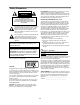
Safety Precautions CAUTION RISK OF ELECTRIC SHOCK DO NOT OPEN CAUTION: TO REDUCE THE RISK OF ELECTRIC SHOCK DO NOT REMOVE COVER (OR BACK) NO USER-SERVICEABLE PARTS INSIDE REFER SERVICING TO QUALIFIED SERVICE PERSONNEL. This lightning flash with arrowhead symbol within an equilateral triangle is intended to alert the user to the presence of uninsulated dangerous voltage within the product’s enclosure that may be of sufficient magnitude to constitute a risk of electric shock to persons.
CAUTION: PLEASE READ AND OBSERVE ALL WARNINGS AND INSTRUCTIONS IN THIS OWNER’S MANUAL AND THOSE MARKED ON THE UNIT. RETAIN THIS BOOKLET FOR FUTURE REFERENCE. This set has been designed and manufactured to assure personal safety. Improper use can result in electric shock or fire hazard. The safeguards incorporated in this unit will protect you if you observe the following procedures for installation, use, and servicing. This unit does not contain any parts that can be repaired by the user.
Table of Contents Introduction Safety Precautions . . . . . . . . . . . . . . . . . . . . . . . . . 2 IMPORTANT SAFETY INSTRUCTIONS . . . . . . . . . . 3 Table of Contents . . . . . . . . . . . . . . . . . . . . . . . . . . 4 Before Use . . . . . . . . . . . . . . . . . . . . . . . . . . . . . . 5-6 Playable Discs . . . . . . . . . . . . . . . . . . . . . . . . . . . 5 Precautions . . . . . . . . . . . . . . . . . . . . . . . . . . . . . 6 Notes on Discs . . . . . . . . . . . . . . . . . . . . . . . . . .
Before Use Video CD (VCD) (8 cm / 12 cm disc) Regional code of the DVD player and DVDs This DVD player is designed and manufactured for playback of region “1” encoded DVD software. The region code on the labels of some DVD discs indicates which type of player can play those discs. This unit can play only DVD discs labeled “1” or “ALL”. If you try to play any other discs, the message “Check Regional Code” will appear on the TV screen.
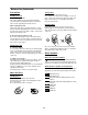
Before Use (Continued) Precautions Handling the unit When shipping the unit The original shipping carton and packing materials come in handy. For maximum protection, re-pack the unit as it was originally packed at the factory. When setting up the unit The picture and sound of a nearby TV, VCR, or radio may be distorted during playback. In this case, position the unit away from the TV, VCR, or radio, or turn off the unit after removing the disc. Storing discs After playing, store the disc in its case.
Front Panel and Display Window N x STOP ( ) Stops playback. 1 ON/STANDBY ( @ / ) Switches the player ON and OFF. X TOP MENU Displays the discs Title menu, if available. PAUSE ( ) Pause playback temporarily/ press repeatedly for frame-by-frame playback. MENU Accesses menu on a DVD disc. > Forward SKIP ( ) Go to NEXT chapter/track. Press and hold for two seconds for a fast forward search. . RETURN - Removes the setup menu.
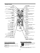
Remote Control SETUP Accesses or removes setup menu. ON/STANDBY Switches DVD Player ON and OFF. OPEN/CLOSE Opens and closes the disc tray. E.A.M. Selects sound mode during disc playback. 0-9 number buttons Selects numbered items in a menu. PROGRAM Enters to the program edit mode or exits from that. FL DIM Controls the Display Window’s light. CLEAR Removes a track number on the program list or a mark on the MARKER SEARCH menu. TOP MENU • Displays the discs Title menu, if available.
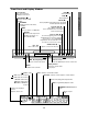
COAXIAL (Digital audio out jack) Connect to digital (coaxial) audio equipment. AUDIO OUT (Left/Right) Connect to an amplifier, receiver, or stereo system. 5.1 CHANNEL AUDIO OUT Connect to a 5.1 channel receiver – center speaker connection – subwoofer connection – front speakers connections – rear (surround) speakers connections VIDEO OUT Connect to a TV with video inputs. COMPONENT/PROGRESSIVE SCAN VIDEO OUT (Y Pb Pr) Connect to a TV with Y Pb Pr inputs. S-VIDEO OUT Connect to a TV with S-Video inputs.
Connections z z z Tips Depending on your TV and other equipment you wish to connect, there are various ways you could connect the player. Use only one of the connections described below. Please refer to the manuals of your TV, VCR, Stereo System or other devices as necessary to make the best connections. For better sound reproduction, connect the player’s AUDIO OUT jacks to the audio in jacks of your amplifier, receiver, stereo or audio/video equipment. See “Connecting to Optional Equipment” on page 11.
Connecting to Optional Equipment Notes – If the audio format of the digital output does not match the capabilities of your receiver, the receiver will produce a strong, distorted sound or no sound at all. – Six Channel Digital Surround Sound via digital connection can only be obtained if your receiver is equipped with a Digital Multi-channel decoder. – To see the audio format of the current DVD in the onscreen display, press AUDIO.
Before Operation Temporary Feedback Field Icons General Explanation This manual gives basic instructions for operating the DVD Player. Some DVDs require specific operation or allow only limited operation during playback. When this occurs, the symbol appears on the TV screen, indicating that the operation is not permitted by the DVD Player or is not available on the disc. TITLE General playback status can be displayed on the TV screen. Some items can be changed on the menu.
Before Operation (Continued) DVD-A Items 4 to select desired item) Function (Press 3/4 Selection Method 2 /6 Shows the current group number and total number of groups, and skips to the desired group number. 1 / 2, or Numbers, SELECT/ENTER 1 /12 Shows the current track number and total number of tracks, and skips to the desired track number. 1 / 2, or Numbers, SELECT/ENTER Group Number Track Number Time search DVD Audio Output mode 0:10:15 1 PPCM 5 CH Shows the elapsed playing time.
Before Operation (Continued) Initial Settings Picture You can set your own Personal Preferences on the player. TV Aspect DVD-A 4:3 Letterbox: Select when a standard 4:3 TV is connected. Displays theatrical images with masking bars above and below the picture. 4:3 Panscan: Select when a conventional TV set is connected. The video material formatted in the Pan & Scan style is played back in that style (Both sides of the picture are cut off). 16:9 Wide: Select when a 16:9 wide TV is connected.
Before Operation (Continued) Sound 5.1 Speaker settings Digital Audio Output Select speaker settings, including volume balance and delay time, or test the speaker settings. Speaker settings are only active on the Analog MultiChannel Output. (See “Speaker Settings”, page 27.) DOLBY DIGITAL/PCM: Select “DOLBY DIGITAL/PCM” if you connected the DVD Player’s DIGITAL OUT jack to a Dolby Digital decoder (or an amplifier or other equipment with a Dolby Digital decoder).
Before Operation (Continued) Others Pluge (Blacker than Black) The DRC, Vocal, PBC, Auto Play, B.L.E., Pluge and DNR settings can be changed. z Press v/V to select the desired item and press ENTER. The setting of the selected item is changed between On and Off. For proper adjustment of your television brightness settings utilizing a commercially available test disc. DVD-V On: Select when you adjust the level of your TV using a commercially available test disc that contains pluge signals.
Before Operation (Continued) Parental Control Area Code Rating Enter the code of a country/area whose standards were used to rate the DVD video disc, referring to the list (See “Area Code List”, page 30.). Movies on DVDs may contain scenes not suitable for children. Therefore, discs may contain Parental Control information that applies to the complete disc or to certain scenes on the disc.
Operation with DVD and Video CD Playing a DVD and Video CD Playback Setup z z DVD-V DVD-A VCD2.0 General Features VCD1.1 Turn on the TV and select the video input source connected to the DVD player. Audio system: Turn on the audio system and select the input source connected to the DVD player. 1 your chosen disc in the tray, with the 2 Load playback side down. OPEN/CLOSE to close the tray. 3 Press READING appears on the TV screen, and playback starts automatically.
Operation with DVD and Video CD 3 To cancel the sequence, press A-B RPT. General Features (continued) Still Picture and Frame-by-frame playback VCD2.0 DVD-A VCD1.1 1 Press PAUSE/STEP during playback. The player will now go into PAUSE mode. 2 You can advance the picture frame-by-frame by pressing PAUSE/STEP repeatedly on the remote control. Note When using a DVD audio disc that includes pictures, this operation may be permitted in some picture segments. Slow Motion DVD-V DVD-A VCD2.0 VCD1.
Operation with DVD and Video CD 2 Press b /B to select the Marker number that you want to erase. 3 Press CLEAR. General Features (continued) Selecting the sound enhancement DVD-V VCD2.0 NORM. VCD1.1 3D SUR The Marker number will be erased from the list. 4 Repeat steps 2 and 3 to erase additional Marker numbers. 5 To remove the MARKER SEARCH menu, press SEARCH. DIALOGUE Press E.A.M. to select the sound enhancement during playback. Special DVD Features NORM.
Operation with DVD and Video CD DVD-A Viewing another PAGE DVD Audio is a new disc format building on the success of DVD to provide high quality, uncompressed, multichannel audio for a new experience in audio quality. A DVD Audio disc can be identified by the DVD audio logo on the disc jacket or on the disc itself. DVD Audio can provide higher quality stereo than Audio CDs with a sampling rate of up to 192kHz (compared to 44.1kHz for CDs).
Operation with Audio CD and MP3/WMA Disc Notes on MP3/WMA Recordings Playing an Audio CD and MP3/WMA Disc CD MP3 About MP3 WMA z The DVD Player can play MP3/WMA formatted recordings on CD-ROM, CD-R or CD-RW discs. Before playing MP3/WMA recordings, read the notes on MP3/WMA Recordings on right. 1 Insert a disc and close the tray. Audio CD; Audio CD menu appears on the TV screen go to step 4. MP3/WMA disc; The MP3/WMA-JPEG choice menu appears on the TV screen.
Operation with Audio CD and MP3/WMA Disc (Continued) CD MP3 Repeat A-B WMA 1 Press PAUSE/STEP during playback. CD 2 To return to playback, press PLAY or press PAUSE/STEP again. To repeat a sequence. 1 During disc playback, press A-B RPT at your desired starting point. Moving to another Track 2 Press A-B RPT again at your desired end point. The Repeat icon and “A * ” appears on the menu screen. WMA CD MP3 >. .
Operation with JPEG Disc Viewing a JPEG disc .> Moving to another File JPEG Press SKIP or once during viewing a picture to advance to the next file or to the previous file. This DVD Player can play discs with JPEG files. Before playing JPEG recordings, read the notes on JPEG Recordings on right. 1 Still Picture 1 Press PAUSE/STEP during slide show. The player will now go into PAUSE mode. 2 To return to the slide show, press PLAY or press PAUSE/STEP again. Insert a disc and close the tray.
VCD2.0 CD VCD1.1 Programmed Playback with Audio CD and MP3/WMA Disc WMA Programmed Playback with Video CD The Program function enables you to store your favorite tracks from any disc in the player memory. Program can contain 30 tracks. 1 MP3 Press PROGRAM during playback or in the stop mode to enter the Program Edit mode. Note On a Video CD with PBC, you must set PBC to Off on the setup menu to use the Program function. See page 16. 1 Insert Video CD and close the tray.
Additional Information Screen Saver Video Mode Setting The screen saver picture appears when you leave the DVD Player in stop mode for about five minutes. After the Screen Saver has been engaged for about five minutes, the DVD Player will automatically turn itself off. DVD-V VCD2.0 VCD1.1 z With certain discs, the playback picture may be flickering or Dot Crawl is shown on straight lines. That means Vertical interpolation or De-interlace is not perfectly matched with the disc.
Speaker Settings Make the following settings for the built-in 5.1 channel surround decoder. If you connected speakers to your DVD Player, setting the Distance lets the speakers know how far the sound has to travel to reach your set listening point. This allows the sound from each speaker to reach the listener at the same time. (1 ft = 30.
Troubleshooting Check the following guide for the possible cause of a problem before contacting service. Cause Symptom Correction No power. z The power cord is disconnected. z Plug the power cord into the wall outlet securely. The power is on, but the DVD player does not work. z No disc is inserted. z Insert a disc. (Check that the DVD or, audio CD indicator in the display window is lit.) No picture. z The TV is not set to receive DVD signal output.
Language Code List Code Language Code Language Code Language Code Language 6566 Abkhazian 7074 Fiji 7678 Lingala 8373 Singhalese 6565 Afar 7073 Finnish 7684 Lithuanian 8375 Slovak 6570 Afrikaans 7082 French 7775 Macedonian 8376 Slovenian 8381 Albanian 7089 Frisian 7771 Malagasy 8379 Somali 6577 Ameharic 7176 Galician 7783 Malay 6983 Spanish 6582 Arabic 7565 Georgian 7776 Malayalam 8385 Sudanese 7289 Armenian 6869 German 7784 Maltese 8387 Swahil
Area Code List Enter the appropriate code number for the initial setting “Area Code” (See page 17).
Specifications General AC 120V, 60 Hz Power consumption 14W Dimensions (approx.) 430 X 60 X 242 mm (16.9 x 2.4 x 9.5 inches) (w x h x d) Mass (approx.) 2.4 kg (5.
LIMITED WARRANTY DVD VIDEO PLAYER Toshiba America Consumer Products, Inc. (“TACP”) and Toshiba Hawaii, Inc. (“THI”) make the following limited warranties to original consumers for DVD Players purchased and used in the United States. THESE LIMITED WARRANTIES EXTEND TO THE ORIGINAL CONSUMER PURCHASER OR ANY PERSON RECEIVING THIS DVD PLAYER AS A GIFT FROM THE ORIGINAL CONSUMER PURCHASER AND TO NO OTHER PURCHASER OR TRANSFEREE. PRODUCTS PURCHASED IN THE U.S.A.
LIMITATION OF IMPLIED WARRANTIES Time for Taking Action ALL WARRANTIES IMPLIED BY THE LAW OF ANY STATE OF THE U.S.A., INCLUDING THE IMPLIED WARRANTIES OF MERCHANTABILITY AND FITNESS FOR A PARTICULAR PURPOSE, ARE EXPRESSLY LIMITED TO THE DURATION OF THE LIMITED WARRANTIES SET FORTH ABOVE.
PRODUCT SAFETY SERVICING GUIDELINES FOR VIDEO PRODUCTS CAUTION : DO NOT ATTEMPT TO MODIFY THIS PRODUCT IN ANY WAY, NEVER PERFORM CUSTOMIZED INSTALLATIONS WITHOUT MANUFACTURER’S APPROVAL. UNAUTHORIZED MODIFICATIONS WILL NOT ONLY VOID THE WARRANTY, BUT MAY LEAD TO YOUR BEING LIABLE FOR ANY RESULTING PROPERTY DAMAGE OR USER INJURY. SERVICE WORK SHOULD BE PERFORMED ONLY AFTER YOU ARE THOROUGHLY FAMILIAR WITH ALL OF THE FOLLOWING SAFETY CHECKS AND SERVICING GUIDELINES.
SERVICING PRECAUTIONS CAUTION : Before servicing the DVD covered by this service data and its supplements and addends, read and follow the SAFETY PRECAUTIONS. NOTE : if unforeseen circumstances create conflict between the following servicing precautions and any of the safety precautions in this publications, always follow the safety precautions. Remembers Safety First: General Servicing Precautions 1.
SECTION 2 CABINET & MAIN CHASSIS CONTENTS 1. EXPLODED VIEWS ................................................................................................................2-2 1. Cabinet and Main Frame Section ...........................................................................................2-2 2. Packing Accessory Section ....................................................................................................
EXPLODED VIEWS 463 1. Cabinet and Main Frame Section 463 250 5 261 467 A49 260 463 A43 463 A48 SCART&5.
2.
SECTION 3 ELECTRICAL CONTENTS ELECTRICAL TROUBLESHOOTING GUIDE......................................................................3-2 1. Power check flow.....................................................................................................................3-2 2. System operation flow ............................................................................................................3-3 3. Test & debug flow ..............................................................................
ELECTRICAL TROUBLESHOOTING GUIDE 1. Power check flow A. B. No VF+ Is 5.2VA section working? No 5V_A . NO NO YES YES Check F102 No 5.2VA. NO Is 5.2V present at emitter of Q107? YES YES Replace D109. Is 5.2VA section working? Check F101 Replace Q107. YES Is there a DC voltage at R101? NO NO Is there a DC voltage At (+) terminal of BD101? YES Replace IC101. 3-2 Replace R101. YES NO Replace BD101.
2. System operation flow Power On 1. 8032 initializes SERVO, DSP & RISC registers 2. Write RISC code to SDRAM 3. Reset RISC Show LOGO Yes Tray Closed? No Tray Close to Closed position SLED at Inner Side? Yes No SLED Moves to Inner Position 1. Judge whether have disc and disc type 2. Jump to related disc reading procedure Recieve OPEN/ CLOSE Key? No 1. Execute Pressed Key & IR Key 2. Systemoperati on Routi ne Loop 1. Stop Playback & Open Tray 2.
3. Test & debug flow TEST Check the AC Vol tage Power PCBA (110V or 220V) No Check the POWER PART Yes Switch on the Power PCBA Is the DC Vol tage outputs OK? (5V, 3.3V, 8V, 12V) No Check the POWER PART Yes Make sure the main PCBA don’t Is 3.3V and 2.5V DC outputs normal on main PCBA? No Check the regulators or diode( D670).
A RESET or Power On. Show LOGO? Flash Memory operates properly? Check connecti on lines between FLASH & MT1379 and the FLASH access time whether is sui table or not. SDRAM works properl y? Check connection lines between SDRAM(IC502,IC503) & MT1379 and the SDRAM is damaged. MT1379 VIDEO outputs properly? Check the rel ated ci rcui t of MT1379. (IC501 PIN 161,166, 168 check) Have TV signal output? Check the fi l teri ng and amp ci rcui t of TV si gnal .(IC604) Check AV cable connection to TV set .
B Does the SLED move No to inner side when it is at outter positi on? Yes Motor Driver STBY Pin is High? No Check the connection line of STBY signal . No Check the rel ated circuit of FMSO. No Check the amp circuit on motor driver. Yes Motor Driver STBY Pin is High? Yes SL+ and SL- output properl y? Yes Do not put in disc and tray close. Check the cable connection with MECHA.
C Laser turns on when reading disc? No Yes LD01 or LD02 output properly? No Check the laser power circuit on MT1336 and connecting to power transistor. (Q204, Q205) No Check therel ated ci rcuit on laser power transi stor Yes Collector voltage of power transistor is OK? ( Q204, Q205) Yes Check cable connection between transistor couput and pick-up head. Put disc in? No Laser off Yes Disc ID is correct? No Proper RFL signal on MT1336? No Check the related circuit on MT1336 RFL signal .
D Yes Focus ON OK? No Proper signals on A, B, C, D of MT1336 No Check connections between MT1336 and pick-up head. No Check the related circuit on MT1336 FEO sugnal . Yes Yes Proper FEO signal on MT1336? Yes Check FEO connection between MT1336 and MT1379 Proper FEO signal on MT1336? Track On OK? No Check the related circuit on MT1336 Yes Yes Properly TRSO signal on MT1379? No Check the TRSO connection on MT1379 and motor dirver.
E Normal Audio output when disc playback? Audio DAC received correct data stream? Check connection between MT1379 & Audio DAC. (Check VRST#, ACLK, ABCK, ASDAT3) Normal Audio DAC out? (IC601) Check the related circuit of Audio DAC. (Check Audio out Pin 14, 15,18,19) Check Audio filter, amplify, mute circuit. (IC602 Application circuit)? Normal IR. VFD & Front pannel key functions? Communications between IR.
DETAILS AND WAVEFORMS ON SYSTEM TEST AND DEBUGGING 1. SYSTEM 27MHz CLOCK,RESET,FLASH R/W SIGNAL 1) MT1379 main clock is at 27MHz(X501) 3.8V, 27MHz FIG 1-1 2) MT1379 & MT1336 reset is high active. Power Cord in 5.
3) RS232 waveform during procedure(Downloading) TXD(J6 PIN3) RXD(J6 PIN 2) FIG 1-3 4) Flash R/W enable signal during download(Downloading) FRD(IC5A1 PIN 28) FWR(IC5A1 PIN 11) FIG 1-4 3-11
2. SDRAM CLOCK 1) MT1379 main clock is at 27MHz(X501) DCLK = 93MHz, Vp-p=2.2, Vmax=2.7V (IC502,IC503 PIN 35) FIG 2-1 3.
2) Tray close waveform OPEN((CN203 PIN 3) CLOSE(CN203 PIN 2) TROPEN(IC202 PIN 1) TRCLOSE(IC202 PIN 2) FIG 3-2 3) Tray open waveform OPEN((CN203 PIN 3) CLOSE(CN203 PIN 2) TROPEN(IC202 PIN 1) TRCLOSE(IC202 PIN 2) FIG 3-3 3-13
4. SLED CONTROL RELATED SIGNAL (NO DISC CONDITION) FMSO(2.0V/1.4V/1.0V) (IC501 PIN 19) STBY(5V) – (IC201 PIN 50) SL+(4.7V/3.6V/1.9V) (IC202 PIN 12) SL-(5.3V/3.7V/2.5V) (IC202 PIN 13) FIG 4-1 5. LENS CONTROL RELATED SIGNAL(NO DISC CONDITION) FOSO(1.5V/1.4V/1.3V) (IC501 PIN 12) F+(4.0V/3.6V/3.2V) (IC202 PIN 9) F-(4.0V/3.6V/3.
6. LASER POWER CONTROL RELATED SIGNAL(NO DISC CONDITION) MDI1(0V/180mV) (IC201 PIN 124) LD01(5.0V//3.5V) IC201 PIN 125) LD02(5.0V/3.6V) (IC201 PIN 126) FIG 6-1 7.
F+(IC202 PIN 9) FE(IC201 PIN 18) RFL(IC201 PIN 19) FIG 7-2 (DVD) F+(IC202 PIN 9) FE(IC201 PIN 18) RFL(IC201 PIN 19) FIG 7-3 (CD) 3-16
F+(IC202 PIN 9) FE(IC201 PIN 18) RFL(IC201 PIN 19) FIG 7-4 (CD) 8.
FE(IC201 PIN 18) FOSO(IC501 PIN12) F+(IC202 PIN 9) F-(IC202 PIN 8) FIG 8-2 (CD) 9. SPINDLE CONTROL WAVEFORM (NO DISC CONDITION) DMSO(1.4V/1.8V) (IC501 PIN 18) SP-(3.6V/2.4V) (IC202 PIN 10) SP+(3.6V/4.
10.
11. RF WAVEFORM RFOP(2.3V/1.1V) (IC201 PIN 6) RFON(0.8V/2.0V) (IC201 PIN 7) FIG 11-1 12.
13. MT1379 VIDEO OUTPUT WAVEFORM 1) Full colorbar signal(CVBS) DCLK = 93MHz, Vp-p=2.2, Vmax=2.
3) C DCLK = 93MHz, Vp-p=2.2, Vmax=2.7V (IC604 PIN 26) FIG 13-3 14.
2) Audio related Signal ASDATA3 ASDAT3(IC501 PIN 157) ABCK(IC501 PIN 148) ALRCK(IC501 PIN 149) FIG 14-2 3-23
M LOAD+,LOAD- 3-24 F+,F-,T+,T°‹ +P8V V25 3V3M AV33 +12V KEY Input 6MHz X-TAL RC901 REMOCON RECEIVER IC903 RESET IC 27MHz X-TAL R/Pr G/Y B/Pb IC604 MM1623XFBE VIDEO BUFFER VCC Y[1:6] 12V DV33 DIG901 FLD DISPLAY IC901 GMS81C2012(Hynix) Front Micom BUFFER IC 74HCT244 VFD_SCK VFD_TXD M_REQ VFD_RXD VCC S_REQ IC510 MUTE AVCC VCC PWRCTL IC501 MT1379E DSP/MPEG ASPDIF RVCC VCC SCLK,SDEN,SDATA PWMOUT2 URST 5V 5V2A -27VA VF- VF+ IC201 MT1336E RF RFON,RFOP,FEO,RFL,CSO TEO,BDO,RFR
SWITCHING IC RECTIFIER 3-25 AC90~240V TRANS FEED B. LPF LPF RECTIFIER(5.2V) RECTIFIER(3.8V) REG(3.3V) REG(8V) REG(12V) PWR ON/OFF LPF LPF RECTIFIER(9V) RECTIFIER(14V) RECTIFIER(FLD) ON/OFF 3.3V/3.3V_M 5V_A 5.2VA 8V 12V -29VA VF- VF+ 2.
M/D PICK UP 3-26 LOAD+, LOAD- SL+, SL- SP+, SP- F+, F-, T+, T- LIMIT,TRIN,TROUT DVD: A,B,C,D, RFO CD: A,B,C,D, E, F,RFO V20 LD0 1, LDO 2, IOA MDI 1 ALPC IC202 LA6560 Motor Driver TRCLOSE STBY,V1P4 IC201 MT1336E RF Signal Processor FOSO,TRSO,FMSO DMSO,,TROPEN ADIN FEO,TEO,RFL,RFRP BDO,CSO,HTRC,V2P8 RFOP,RFON IC302 GM72V161621 1M x 16bit SDRAM MA[0:10] DQM0 ,DQM1 WE#,CAS#,RAS# CS#,BA0, DCLK DCKE IC501 MT1379 DVDPLAYER COMBO CHIP 27MHz X-TAL RXD, TXD SCL, SDA PRD#, PWR# PCE# A[0:19] A
3-27 RF IC Interface FEO,CSO,TEO,ADIN,BDO SDATA,SDEN,SCLK,URST FMSO,DMSO V1P4,V2P8 TROPEN,TRSO,FOSO ACLK,ABCK ALRCK URST,S_REQ VFD_RXD DCLK,WE,CAS,RAS CS,DCKE,MA[0:10] DQM0,DQM1 IC501 (MPEG + DSP) MT1379 X501 27MHz FRONT MICOM Interface (FRONT BOARD) RFOP,RFON,HTRC,RFRP,RFL AMDAT IC5K1 A/D Con.
MPEG MP EG MPEG MPEG 3-28 ADATA3 ADATA2 ADATA1 SDA SCL ACLK DAC RESET ADATA3 SDA SCL ACLK DAC RESET (Y/C) (R.G.B) / (Y.Pb.Pr ) IC301 AUDIO DAC (5.1CH) 5.1CH BOARD IC601 AUDIO DAC (2CH) IC604 VIDEO 6dB Amp IC304 (OP Amp) LPF&Buffer IC303 (OP Amp) LPF&Buffer IC302 (OP Amp) LPF&Buffer IC602 (OP Amp) LPF&Buffer SUPER VIDEO (Y/C) WOOFER CENTER REAR ‘L’ FRONT ‘L’ REAR ‘R’ FRONT ‘R’ AUDIO ‘R’ AUDIO ‘R’ COMPONENT (R.G.B) / (Y.Pb.Pr ) CVBS A/V JACK 5.
CIRCUIT DIAGRAMS IMPORTANT SAFETY NOTICE WHEN SERVICING THIS CHASSIS, UNDER NO CIRCUMSTANCES SHOULD THE ORIGINAL DESIGN BE MODIFIED OR ALTERED WITHOUT PERMISSION FROM THE TOSHIBA ELECTRONICS CORPORATION. ALL COMPONENTS SHOULD BE REPLACED ONLY WITH TYPES IDENTICAL TO THOSE IN THE ORIGI- 1. POWER(SMPS) CIRCUIT DIAGRAM NAL CIRCUIT. SPECIAL COMPONENTS ARE SHADED NOTE : ON THE SCHEMATIC FOR EASY IDENTIFICATION. 1. Shaded( ) parts are critical for safety.
2. SYSTEM CIRCUIT DIAGRAM No Power on Video signal not appeared AUDIO DAC interface VIDEO interface System not working or screen is abnormal RF & MOTOR DRIVE interface System not working or Digitron not display System not operate Digitron all not display System not working Program download fail Video signal Y '02. 12.
3. RF & SERVO CIRCUIT DIAGRAM CD/DVD LD will not on '02. 12.
4. TIMER, 5.1CH, SCART, KARAOKE CIRCUIT DIAGRAM Power LED abnormal (OPTIONAL PART) Karaoke not operate. Remocon not operate System not operate System not operate or Digitron abnormal or Key not operate. Digital abnormal (OPTIONAL PART) (OPTIONAL PART) 5.1CH Audio Bad '03. 3.
5. AV/JACK CIRCUIT DIAGRAM All Video signal isn't appear or bad 2CH Audio out bad. SACD OPTION 2.5V doesn't appeat System not working 2CH Audio out bad. Video Signal Y Video Signal CVBS Video Signal Color 2CH Audio '02. 12.
• CIRCUIT VOLTAGE CHART IC201(MT1336E) PIN STOP PLAY 1 1.03 2.99 2 5.11 5.08 3 0 0 4 0 0 5 5.11 5.07 6 0 1.95 7 0 0 8 0 0 9 5.11 0 10 5.11 5.08 11 5.11 5.08 12 0 0 13 5.11 0 14 5.11 5.08 15 2.84 2.81 16 1.45 1.43 17 2.08 2.07 18 1.37 1.42 19 0.69 2.3 20 2.4 0 21 2.35 0 22 5.11 5.08 23 0 0 24 2.59 3.2 25 0.19 1.88 26 1.58 0 27 2.56 3.13 28 2 2.01 29 2 2.06 30 2.96 1.52 31 0 0 32 0.06 2.07 33 0.07 2.07 34 0 0 35 0 0 36 0 0 37 5.13 0 38 0 0 39 0 0 40 0 0 41 0 0 42 5.12 5.09 43 5.12 5.09 44 5.12 5.09 45 5.
IC201(MT1336E) IC202(MOTOR) IC501(MT1379) PIN STOP PLAY STOP PLAY STOP 161 0 162 0 163 0 164 0 165 0 166 0 167 0 168 0 169 0 170 0 171 0 172 3.01 173 0 174 0 175 0 176 0 177 0 178 0 179 0 180 0 181 2.04 182 0 183 0 184 0 185 0 186 187 0 188 0 189 0 190 0 191 0.23 192 0 193 0 194 0 195 0 196 0 197 0 198 0 199 0 200 0 201 0 202 0 203 0 204 0 205 0 206 0 207 0 208 0 209 0 210 0 211 0 212 0 213 0 214 0 215 1.
PRINTED CIRCUIT DIAGRAMS 1. MAIN P.C.
2. KEY P.C.BOARD (Solder Side) 3. TIMER P.C.
4. SMPS P.C.BOARD 5. 5.1CH P.C.
SECTION 4 MECHANISM OF DVD PART CONTENTS DECK MECHANISM PARTS LOCATIONS • Top View..................................................4-1 • Top View(without Tray Disc) .................4-1 • Bottom View ...........................................4-1 5. Frame Assembly Up/Down ..............4-4 6. Belt Loading......................................4-4 7. Gear Pulley .......................................4-4 8. Gear Loading ....................................4-4 9. Guide Up/Down................................
DECK MECHANISM PARTS LOCATION • Top View (With Tray) Procedure Parts Fixing Type Starting No.
DECK MECHANISM DISASSEMBLY Fig. 4-1 Fig. 4-2 1. Holder Clamp (Fig. 4-1) 2. Tray Disc (Fig. 4-2) 1) Release 2 Screws(S1). 2) Unhook 2 Locking Tabs(L1). 3) Lift up the Holder Clamp and then separate it from the Base Main. 1-1. Clamp Assembly Disc 1) Place the Clamp Assembly Disc as Fig. (A) 2) Lift up the Clamp Assembly Disc in direction of arrow(A). 3) Separate the Clamp Assembly Disc from the Holder Clamp. 1-1-1.
DECK MECHANISM DISASSEMBLY Fig. 4-3 3. Base Assembly Sled (Fig. 4-3) 3-3. Gear Assembly Rack 1) Release the Scerw(S3) 1) Release 4 Screw(S2). 2) Disconnect the FFC Connector(C1) 3-1. Gear Assembly Feed 3-2. Gear Assembly Middle 4. Rubber Rear (Fig.
DECK MECHANISM DISASSEMBLY Fig. 4-4 5. Frame Assembly Up/Down (Fig. 4-4) Note Put the Base Main face down(Bottom Side) 1) Release the Screw(S4) 2) Unlock the Locking Tab(L3) in direction of arrow and then lift up the Frame Assembly Up/Down to separate it from the Base Main. Note • When reassembling move the Guide Up/Down in direction of arrow(C) until it is positioned as Fig.(C). • When reassembling insert (A) portion of the Frame Assembly Up/Down in the (B) portion of the Guide Up/Down as Fig.(B) 6.
EXPLODED VIEWS 1.
NOTES) NOTES) NOTES) NOTES) Warning Parts that are shaded are critical With respect to risk of fire or electricial shock. SECTION 5 REPLACEMENT PARTS LIST TOSHIBA MODEL : SD-4900-S-TU/SD-4900-S-TC S AL LOCA. NO. TOSHIBA PART LG PART NO. DESCRIPTION NSP : Not avallable as service parts.
S AL LOCA. NO. TOSHIBA PART LG PART NO. DESCRIPTION SPECIFICATION R908 79093029 0RH1002C622 RESISTOR,METAL GLAZED(CHIP) 10K OHM 1 / 16 W 1608 5.00% D R909 79093029 0RH1002C622 RESISTOR,METAL GLAZED(CHIP) 10K OHM 1 / 16 W 1608 5.00% D R910 79093042 0RH3301C622 RESISTOR,METAL GLAZED(CHIP) 3.3K OHM 1 / 16 W 1608 5.00% D R911 79093041 0RH3300C622 RESISTOR,METAL GLAZED(CHIP) 330 OHM 1 / 16 W 1608 5.00% D R913 79098771 0RH2200C622 RESISTOR,METAL GLAZED(CHIP) 220 OHM 1 / 16 W 1608 5.
S AL LOCA. NO. TOSHIBA PART LG PART NO. DESCRIPTION *** DECK ASSEMBLY SPECIFICATION REMARKS *** A00 79096645 6721RH0370A DECK ASSEMBLY,VIDEO DECK/MECHA DP-7(55) MITSUMI GO A01 AF000173 4861R-0016B CLAMP ASSEMBLY DISC DP7 - SH NSP A02 79096682 3041R-M003B BASE ASSEMBLY MAIN(DP-7R) - SH A03 AF000163 3041R-M002B BASE ASSEMBLY SLED DP7(MIT 502W-GOLD) - SH 001 79097006 3300R-0547A PLATE CLAMP 002 79097007 5016H-1016B MAGNET CLAMP(LDM-R608,10*5,1*1.
S AL LOCA. NO. TOSHIBA PART LG PART NO. DESCRIPTION SPECIFICATION C232 79092014 0CH1104K942 CAPACITOR,CHIP[CERAMIC M/L HD 0.1UF 50V Z Y5V(F) 1508 R/TP C233 79092014 0CH1104K942 CAPACITOR,CHIP[CERAMIC M/L HD 0.1UF 50V Z Y5V(F) 1508 R/TP C234 79092014 0CH1104K942 CAPACITOR,CHIP[CERAMIC M/L HD 0.1UF 50V Z Y5V(F) 1508 R/TP C239 79092014 0CH1104K942 CAPACITOR,CHIP[CERAMIC M/L HD 0.1UF 50V Z Y5V(F) 1508 R/TP C240 79096609 0CH1153K562 CAPACITOR,FIXED CERAMIC(Temp.c 0.
S AL LOCA. NO. TOSHIBA PART LG PART NO. DESCRIPTION SPECIFICATION C518 79092014 0CH1104K942 CAPACITOR,CHIP[CERAMIC M/L HD 0.1UF 50V Z Y5V(F) 1508 R/TP C519 79092014 0CH1104K942 CAPACITOR,CHIP[CERAMIC M/L HD 0.1UF 50V Z Y5V(F) 1508 R/TP C520 79092014 0CH1104K942 CAPACITOR,CHIP[CERAMIC M/L HD 0.1UF 50V Z Y5V(F) 1508 R/TP C521 79092014 0CH1104K942 CAPACITOR,CHIP[CERAMIC M/L HD 0.1UF 50V Z Y5V(F) 1508 R/TP C522 79092014 0CH1104K942 CAPACITOR,CHIP[CERAMIC M/L HD 0.
S AL LOCA. NO. TOSHIBA PART LG PART NO. DESCRIPTION SPECIFICATION C5A8 79092014 0CH1104K942 CAPACITOR,CHIP[CERAMIC M/L HD 0.1UF 50V Z Y5V(F) 1508 R/TP C5A9 79092014 0CH1104K942 CAPACITOR,CHIP[CERAMIC M/L HD 0.1UF 50V Z Y5V(F) 1508 R/TP C5D1 79098709 0CE2274C638 CAPACITOR,ELECTROLYTIC 220M SRA 6.3V M FM5 TP(5) C600 79092014 0CH1104K942 CAPACITOR,CHIP[CERAMIC M/L HD 0.
S AL LOCA. NO. TOSHIBA PART LG PART NO. DESCRIPTION SPECIFICATION C6W2 79092014 0CH1104K942 CAPACITOR,CHIP[CERAMIC M/L HD 0.1UF 50V Z Y5V(F) 1508 R/TP C6W3 79097104 0CE1064F638 CAPACITOR,ELECTROLYTIC 10M SRA 16V M FM5 TP(5) C6W4 79097121 0CH4101K412 CHIP CAPA CERAMIC M/L T.C F/S 100P 50V J COG 1.6X0.8 R/TP C6W5 79098721 0CH4270K412 CAPACITOR,CHIP[CERAMIC M/L TC 27PF 50V J NP0 1608 R/TP C6W6 79097121 0CH4101K412 CHIP CAPA CERAMIC M/L T.C F/S 100P 50V J COG 1.6X0.
S AL LOCA. NO. TOSHIBA PART LG PART NO. DESCRIPTION SPECIFICATION R212 79096547 0RJ7503C677 RESISTOR,METAL GLAZED(CHIP) 750K OHM 1/16 W 5% 1608 R/TP R213 79096553 0RH3903C622 RESISTOR,METAL GLAZED(CHIP) 390K OHM 1 / 16 W 1608 5.00% D R214 79096547 0RJ7503C677 RESISTOR,METAL GLAZED(CHIP) 750K OHM 1/16 W 5% 1608 R/TP R215 79096553 0RH3903C622 RESISTOR,METAL GLAZED(CHIP) 390K OHM 1 / 16 W 1608 5.00% D R216 79096565 0RH0101C622 RESISTOR,METAL GLAZED(CHIP) 1 OHM 1 / 16 W 1608 5.
S AL LOCA. NO. TOSHIBA PART LG PART NO. DESCRIPTION SPECIFICATION R529 79093020 0RH0000C622 RESISTOR,METAL GLAZED(CHIP) 0 OHM 1 / 16 W 1608 5.00% D R534 79098767 0RH1001C622 RESISTOR,METAL GLAZED(CHIP) 1K OHM 1 / 16 W 1608 5.00% D R535 79098767 0RH1001C622 RESISTOR,METAL GLAZED(CHIP) 1K OHM 1 / 16 W 1608 5.00% D R536 79093020 0RH0000C622 RESISTOR,METAL GLAZED(CHIP) 0 OHM 1 / 16 W 1608 5.00% D R549 79093045 0RH4701C622 RESISTOR,METAL GLAZED(CHIP) 4.7K OHM 1 / 16 W 1608 5.
S AL LOCA. NO. TOSHIBA PART LG PART NO. DESCRIPTION SPECIFICATION R644 79093020 0RH0000C622 RESISTOR,METAL GLAZED(CHIP) 0 OHM 1 / 16 W 1608 5.00% D R649 79093033 0RH1500C422 RESISTOR,METAL GLAZED(CHIP) 150 OHM 1 / 16 W 1608 1.00% D R652 79093033 0RH1500C422 RESISTOR,METAL GLAZED(CHIP) 150 OHM 1 / 16 W 1608 1.00% D R655 79093033 0RH1500C422 RESISTOR,METAL GLAZED(CHIP) 150 OHM 1 / 16 W 1608 1.00% D R656 79093020 0RH0000C622 RESISTOR,METAL GLAZED(CHIP) 0 OHM 1 / 16 W 1608 5.
S AL LOCA. NO. TOSHIBA PART LG PART NO. DESCRIPTION SPECIFICATION C322 79097104 0CE1064F638 CAPACITOR,ELECTROLYTIC 10M SRA 16V M FM5 TP(5) C323 79097104 0CE1064F638 CAPACITOR,ELECTROLYTIC 10M SRA 16V M FM5 TP(5) C324 79096608 0CH1392K566 CAPACITOR,FIXED CERAMIC(Temp.c 3900P 50V K X7R 2.0X1.
S AL LOCA. NO. TOSHIBA PART LG PART NO. DESCRIPTION SPECIFICATION REMARKS R321 79096346 0RH1003D622 RESISTOR,METAL GLAZED(CHIP) 100K OHM 1 / 10 W 2012 5.00% D R322 79096355 0RH2200D622 RESISTOR,METAL GLAZED(CHIP) 220 OHM 1 / 10 W 2012 5.00% D R323 79096344 0RH1001D622 RESISTOR,METAL GLAZED(CHIP) 1K OHM 1 / 10 W 2012 5.00% D R324 79096355 0RH2200D622 RESISTOR,METAL GLAZED(CHIP) 220 OHM 1 / 10 W 2012 5.
S AL LOCA. NO. TOSHIBA PART LG PART NO. DESCRIPTION SPECIFICATION REMARKS C121 79092005 0CE2276F638 CAPACITOR,ELECTROLYTIC 220U SMS 16V M FM5 TP(5) C122 79092035 624-085D CAPACITOR CE 47UF/50V KME (SMPS) C123 79092003 0CE108BF630 CAPACITOR,FIXED ELECTROLYTIC 1000UF KME 16V M FM5 BULK C124 79098711 0CE337CH618 CAPACITOR,FIXED ELECTROLYTIC 330UF SHL,SD 25V 20% FL TP 5 C126 79092033 0CQ1031Y519 CAPACITOR,POLYESTER 0.
S AL LOCA. NO. TOSHIBA PART LG PART NO. DESCRIPTION SPECIFICATION R112 79096692 0RD0392F608 RESISTOR,FIXED CARBON FILM 39 OHM 1/6 W 5% TA26 R114 79093006 0RD1003F608 RESISTOR,FIXED CARBON FILM 100K OHM 1/6 W 5% TA26 R115 79097165 0RD0182F608 RESISTOR,FIXED CARBON FILM 18 OHM 1/6 W 5.00% TA26 R116 79097165 0RD0182F608 RESISTOR,FIXED CARBON FILM 18 OHM 1/6 W 5.
TOSHIBA CORPORATION 1-1, SHIBAURA 1-CHOME, MINATO-KU, TOKYO 105-8001, JAPAN