TOSHIBA Storage Device Division MK6017MAP (HDD2155) HARD DISK DRIVE PRODUCT SPECIFICATION Rev 00 October 2000 DOCUMENT NUMBER 14603
360014937 No.5T03670-2D TOSHIBA TITLE: 2.5 inch Disk Drives MK6017MAP Product Specification REV 日 付 No. DATE 00 2000-10-06 記 事 CONTENTS Initial issue 部 門 担 当 承 認 DEP. REVISED APP’D D-SETSU2 A.Iwata M.Hattori 保 管 日 STGE.PER. No. 360014937 TOSHIBA CORPORATION CONT.ON 503 Copyright ©2000 Toshiba corporation. All rights reserved. - 502 - PAGE No.
60014937 SAFETY The hard disk drive and product specifications contain essential information for the protection of users and others from possible injury and property damage and to ensure correct handling. Please check that you fully understand the definition of the following messages (signs and graphical symbols) before going on to read the text, and always follow the instructions.
360014937 USAGE RESTRICTIONS ● Since the drive is not designed or manufactured to be used for a system including equipment (*1) directly linked with human life, etc., Toshiba Corporation shall not be liable for this type of use. *1: Equipment directly linked with human life, etc. corresponds to the following. −Medical equipment such as life support systems, equipment used in operations,etc.
360014937 SAFETY ■ Do not disassemble, remodel or repair. Disassembly, remodeling or repair may cause injury, failure, or data loss. ■ Do not drop. Dropping may cause injury. ■ Do not touch sharp edges or pins of the drive. Sharp protrusions etc. may cause injury. Hold the drive by both sides when carrying it. Copyright © 2000 Toshiba corporation. All rights reserved.
360014937 SAFETY Observe the following to prevent failure, malfunction or data loss. NOTE ●Follow the specifications for 6. POWER SUPPLY (page516), 8. ENVIRONMENT (page 522, 523), etc. when using. Failure to do so may cause damage to the drive. ● Observe cautions in 7.4 MOUNTING INSTRUCTION (page517) and 9.6 LOAD / UNLOAD (page525 ) when handling, setting up, or using the drive. ●Take anti-static measures in order to avoid damage to the drive when handling it.
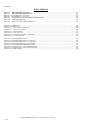
360014937 TABLE OF CONTENTS 1. SCOPE ......................................................................................................................................................................... 511 2. GENERAL DESCRIPTION....................................................................................................................................... 511 3. KEY FEATURES .....................................................................................................................
360014937 10.3.5 Signal Description .....................................................................................................................................531 10.4 HOST INTERFACE TIMING ...................................................................................................................................533 10.4.1 Program I/O Write Timing.........................................................................................................................533 10.4.
360014937 10.9.1 10.9.2 10.9.3 10.9.4 10.9.5 10.10 10.10.1 10.10.2 10.10.3 10.11 10.11.1 10.11.2 10.11.3 10.11.4 10.12 10.13 10.14 10.14.1 10.14.2 10.15 11. 11.1 11.2 11.3 11.4 11.5 11.6 Security mode default setting..................................................................................................................... 609 Initial setting of the user password............................................................................................................
360014937 Table of Figures FIGURE 1 FIGURE 2 FIGURE 3 FIGURE 4 FIGURE 5 FIGURE 6 MK6017MAP DIMENSIONS.............................................................................................................................519 MOUNTING RECOMMENDATION ......................................................................................................................521 ATA INTERFACE CONNECTOR ..............................................................................................................
360014937 1. SCOPE This document describes the specifications of the following model, MK6017MAP of 2.5- inch type Winchester disk drives. . Factory Number Sales Number HDD2155 MK6017MAP 2. GENERAL DESCRIPTION The MK6017MAP which is noted hereinafter as‘‘ a series of intelligent disk drives . MK6017MAP’’or as‘‘ the drive ’’comprises The drive features an ATA-2 / 3 / 4 /5 interface embedded controller that requires a simplified adapter board for interfacing to an AT or AT compatible bus.
360014937 SAFETY ■Do not disassemble, remodel or repair. Disassembly, remodeling or repair may cause injury, failure, or data loss. NOTE ●There is a certain probability of the drive causing failure including data error or data loss. Take preventive steps such as backing up data etc. without exception in order to prevent loss etc. in cases where data loss may result in loss or damage. ●Do not touch the top cover since application of force to it may cause damage to the drive.
360014937 3. KEY FEATURES • High capacity in smallest size . . • 2.5inch-type 1platters accommodating formatted capacity of 6.007GB, Slim ( 9.5 mm in height ) and light (92 gram in weight) design. Fast access and fast transfer rate . Quick spin up of Spindle Motor 4 sec. . Average access time 13 msec enabled by optimized balance of a head actuator assembly and an efficiently designed magnet of rotary VCM. . . • Read ahead cache and write cache enhancing system throughput. Intelligent Interface .
360014937 4. BASIC SPECIFICATION MODEL Formatted Capacity( gigabytes ) Servo design method Recording method Recording density Track / mm (TPI ) Bit / mm ( BPI ) Flux change / mm ( FRPI ) Number of disks Number of data heads Number of user data cylinders Bytes per sector MK6017MAP 6.007 Sector Servo 32/34 TC-MEEPR4+PP 1667 (42.3k) 20.8k (528k ) max. 22.1k(561k ) max. 1 1 24,800 512 Copyright ©2000 Toshiba corporation. All rights reserved.
360014937 5. PERFORMANCE Access time ( msec ) <*1> Track to track seek <*2> Average seek <*3> Max. seek <*4> Rotation speed ( RPM ) Average Latency Time ( msec ) Internal Transfer rate ( Mbits / sec ) Host Transfer rate ( Mbytes / sec ) Ultra DMA mode PIO mode Sector Interleave Track skew Buffer size ( Kbytes ) Cache Start time <*5> ( Up to Drive Ready) Recovery time from Stand- by <*5> Command Overhead ( msec ) 3 13 24 4,200 + 0.1% 7.14 133.0∼253.5 66.7 16.
360014937 6. POWER REQUIREMENTS 6.1 Supply Voltage 6.1.1 Supply for Logic Allowable voltage Allowable noise/ripple 5V + 5% 100 mV p-p or less 6.1.2 Supply for Motor Allowable voltage Allowable noise/ripple 5V + 5% 100 mV p-p or less 6.2 Power Consumption Start Seek (note 7) Read / Write(note 8) Active idle (note 1) Low power idle (note 9) Stand- by (note 2) Sleep Average (note 3) 2.7 W Typical 2.3 W Typical 1.9 W Typical 0.78 W Typical 0.58 W Typical 0.25 W Typical 0.1 W Typical Maximum (note 4) 5.
360014937 7. MECHANICAL SPECIFICATIONS 7.1 Dimension Width Height Depth 69.85mm ( 2.75” ) 9.5 mm ( 0.37”) 100.0 mm ( 3.94” ) Figure 1 and Table 7.4-1 show an outline of the drive. 7.2 Weight 92gram(Typ.) 94gram(max.) 7.3 Drive Orientation The drive can be installed in all axes (6 directions). 7.4 Mounting Instructions SAFETY NOTE ●Take anti-static measures in order to avoid damage to the drive when handling it. The drive uses parts susceptible to damage due to ESD (electrostatic discharge).
360014937 7.4.1 Screwing Four screws should be tightened equally with 0.3 N.m ( 3 kgf.cm ) torque. min. and 3.5 mm maximum. The depth should be 3.0 mm 7.4.2 Installation ① ② ③ ④ The drive should be mounted carefully on the surface of 0.1mm or less flatness to avoid excessive distortion. In order to prevent short-circuit under any circumstances, the space of 0.5mm or more should be kept under the PCB and the design have to be checked carefully (See fig. 2).
360014937 UNIT: mm Figure 1 MK6017MAP Dimensions Copyright © 2000 Toshiba corporation. All rights reserved.
360014937 Dimension A1 A2 SFF-8200 Rev1.1(*) SFF-8201 Rev1.2 SFF-8212 Rev1.2 Millimeters Inches − − − − MK6017MAP (Differences only) Millimeters Inches 9.5 0.374 0.20 A3 0.20 − − A4 69.85 2.750 A5 0.25 0.010 A6 101.85 max 4.010 max 100.00 ±0.41 A9 3.99 0.157 3.99 ±0.43 A10 10.14 0.399 10.14 ±0.51 A11 2.00 0.079 A12 2.00 0.079 A13 0.50 0.020 A14 0.05 0.002 A17 0.50 0.020 A18 0.05 0.002 A21 3.86 0.152 A22 0.20 0.008 A23 3.00 0.118 A26 M3 N/A A28 4.07 0.160 A29 61.72 2.430 61.72 ±0.30 A32 M3 N/A A34 1.
360014937 Figure 2 Mounting Recommendation Copyright © 2000 Toshiba corporation. All rights reserved.
360014937 8. ENVIRONMENTAL LIMITS 8.1 Temperature and Humidity 8.1.1 Temperature Operating 5oC- 55oC Gradient 15oC / Hour maximum Non- operating - 20oC- 60oC Gradient 15oC / Hour maximum Under shipment - 40oC- 70oC Gradient 30oC / Hour maximum ( Packed in Toshiba’s original shipping package. ) The temperature of top cover and base must be kept under 60℃ at any moment to maintain the desire reliability. 8.1.2 Humidity Operating Non- operating Under shipment Max. wet bulb 8%- 90% R.H.
360014937 8.4 Altitude Operating Non operating - 300 m to 3,000 m - 400 m to 15,000 m 8.5 Acoustics(Sound Power) 36 dBA MAX. 39 dBA MAX. For idle mode ( Spindle in rotating ). For repetition of random seek with full cylinder read operation. Measurements are to be taken in accordance with ISO 7779. 8.6 Safety Standards The drive satisfies the following standards . Underwriters Laboratories Canadian Standard Association TUV Rheinland ( UL ) 1950 ( CSA ) C22.2 No.950 EN 60 950 8.
360014937 9. RELIABILITY A failure is defined as an inability of the drive to perform its specified function described in the requirements of this document when being operated under the normal conditions or conditions specified in this document. However , damages caused by operation mistake, mishandling, accidents, system errors and other damages that can be induced by the customers are not defined as failure. . 9.1 Error Rate 9.1.
360014937 9.6 Load/Unload Be sure to issue and complete the following commands for unloading before cutting off the power supply. 300,000 times of normal Load / Unload can be performed by a command. Unload is executed by the following commands : ・Soft Reset ・Standby ・Standby Immediate ・Sleep If the power supply is cut when the head is on a media, Emergency Unload is performed by routing the back-EMF of SPM to the voice coil. In this case, Emergency Unload is performed 20,000 times maximum.
360014937 10. HOST INTERFACE Related Standards Information technology - AT Attachment Interface with Extensions (ATA-2) X3T10.279-199x Information technology - AT Attachment-3 Interface (ATA-3) X3T10/2008D Revision 6 October 26, 1995 Information technology - AT Attachment with Packet Interface Extension (ATA -4) T13/1153D Revision 17 October 30, 1997 Information technology - AT Attachment with Packet Interface-5 Interface-5 (ATA-5) T13/1321D Revision 2 December 13, 1999 10.1 Cabling 10.1.
360014937 10.2 Electrical specification 10.2.1 Cable length and capacitance 0.46m MAX. 35pF MAX. 10.2.2 DC input/output Characteristics 10.2.2.1 Input item voltage high (note 1) low leak current unit V V µA value 2.0 to (supply voltage +0.5 ) -0.3 to 0.8 + 10 (note 2) As non-connected logic voltage, input voltage level is from -0.3V to 0.5V. (note 1) The max. input range of signal is from -0.3V to (supply voltage +0.5V ) (note 2) Except for signal lines pulled up as shown in Table 10.3.3-1 10.2.2.
360014937 10.3 Interface connector 10.3.1 ATA interface connector 2.00 2.00 × 24 = 48.00 Polarity key 43 1 44 2 Figure 3 ATA interface connector Copyright ©2000 Toshiba corporation. All rights reserved.
360014937 10.3.2 Pin Assignment The following table describes all of the pins on the Task File Interface. PIN No. 1 3 SIGNALS - RESET DD 7 Table 10.3-1 Signal pin assignment PIN No.
360014937 10.3.3 Signal Treatment Driver types and requirements for the signal pull- up and down are as follows. Resistor requirement is minimum for the host. - IO16 is pulled up in the drive with certain value so that the Vol is obtained to run with a host that has large value of pull up resistor. - CS0 and - CS1 are also pulled up for better noise immunity. SIGNAL - RESET DD 0:15 Table 10.
360014937 10.3.4 Series resistance Each signal has its own series resistance. SIGNAL SERIAL RESISTANCE VALUE -DIOR -HDMARDY 82Ω HSTROBE -DIOW STOP 82Ω -CS0, -CS1 82Ω DA0,DA1,DA2 82Ω -DMACK 82Ω DMARQ 22Ω INTRQ 22Ω IORDY -DDMARDY DSTROBE 22Ω DD0∼DD15 33Ω 10.3.5 Signal Description SIGNAL DIR.
360014937 CSEL O 28 - DMACK O 29 INTRQ I 31 - IOCS16 I 32 DA 1 - PDIAG /CBLID O I/O 33 34 DA 0 DA 2 - CS0 O O O 35 36 37 - CS1 O 38 - DASP I 39 RESERVED + 5V (LOGIC) + 5V (MOTOR) GROUND 27,44 41 42 2,19 22,24 26,30 40,43 This pin and J2 (see 10.7) are used to determine the drive address, Master or Slave. When J2 is ground, the drive works as a Master and when J2 is open, the drive works as a Slave.
360014937 10.4 Host Interface Timing 10.4.
360014937 10.4.
360014937 10.4.3 Single Word DMA Write Timing tO DMARQ tC -DMACK tI tJ -DIOW tD DD15∼DD0 tG tH ATA-2 SPECIFICATIONS Symbol t0 tC tD tG tH tI tJ Transfer mode Meaning Cycle time DMACK to DMARQ delay -DOW 16-bit -DOW data setup -DOW data hold DMACK to -DOW setup -DOW to DMACK hold MODE 0 Min. 960 Max. MODE 1 Min. 480 200 480 250 50 0 0 Max. MODE 2 Min. 240 100 240 100 30 0 0 Max. 80 120 35 20 0 0 Copyright © 2000 Toshiba corporation. All rights reserved.
0014937 10.4.4 Single Word DMA Read Timing tO DMARQ tC -DMACK tI tJ -DIOR tD DD15∼DD0 tE tS tF ATA-2 SPECIFICATION Symbol t0 tC tD tE tF tI tJ tS Transfer mode Meaning Cycle time DMACK to DMARQ delay -DIOR 16-bit -DIOR data access -DIOR data hold DMACK to -DIOR setup -DIOR to DMACK hold -DIOR setup MODE 0 Min. 960 Max. MODE 1 Min. 480 200 480 5 0 0 tD-tE Max. 100 240 250 5 0 0 tD-tE Max. 80 120 150 5 0 0 tD-tE Copyright ©2000 Toshiba corporation. All rights reserved.
360014937 10.4.5 Multiword DMA Write Timing DMARQ tO tL -DMACK tI tD tK tJ -DIOW DD15∼DD0 tG tH ATA/ATAPI-5 SPECIFICATIONS Symbol t0 tC tD tG tH tI tJ tK tL Transfer mode Meaning Cycle time DMACK to DMARQ delay -DIOW 16-bit -DIOW data setup -DIOW data hold DMACK to -DIOW setup -DIOW to DMACK hold -DIOW negated pulse width -DIOW to DMARQ delay MODE 0 Min. 480 Max. MODE 1 Min. 150 --215 100 20 0 20 215 Max. --- 80 30 15 0 5 50 40 40 MODE 2 Min. Max.
360014937 10.4.6 Multiword DMA Read Timing DMARQ tO tL -DMACK tD tI tJ tK -DIOR tZ tE DD15∼DD0 tF ATA/ATAPI-5 SPECIFICATIONS Symbol t0 tC tD tE tF tZ tI tJ tK tL Transfer mode Meaning Cycle time DMACK to DMARQ delay -DIOR 16-bit -DIOR data access -DIOR data hold -DIOR to tristate DMACK to -DIOR setup -DIOR to DMACK hold -DIOR negated pulse width -DIOR to DMARQ delay MODE 0 Min. 480 Max. MODE 1 Min. 150 --215 Max.
360014937 10.4.7 Ultra DMA Timing Initiating an Ultra DMA data in burst DMARQ (device) tUI DMACK(host) tACK tZAD STOP (host) HDMARDY(host) tFS tENV tACK tFS tENV tZAD tZIORDY DSTROBE (device) tAZ tVDS tDVH DD(15:0) tACK DA0, DA1, DA2, CS0-, CS1- Copyright © 2000 Toshiba corporation. All rights reserved.
360014937 Sustained Ultra DMA data in burst t2CYC tCYC tCYC t2CYC DSTROBE at device tDVH tDVS tDVH tDVS tDVH DD(15:0) at device DSTROBE at host tDH tDS tDH tDS DD(15:0) at host Host pausing an Ultra DMA data in burst DMARQ (device) DMACK(host) tRP STOP (host) tSR HDMARDY(host) tRFS DSTROBE (device) DD(15:0) (device) Copyright ©2000 Toshiba corporation. All rights reserved.
360014937 Device terminating an Ultra DMA data in burst DMARQ (device) tMLI DMACK(host) tLI tACK tLI STOP (host) tACK tLI HDMARDY(host) tSS tIORDYZ DSTROBE (device) tZAH tAZ DD(15:0) tDVS tDVH CRC tACK DA0, DA1, DA2, CS0-, CS1- Copyright © 2000 Toshiba corporation. All rights reserved.
360014937 Host terminating an Ultra DMA data in burst DMARQ (device) tLI tMLI DMACK(host) tZAH tAZ tRP tACK STOP (host) tACK HDMARDY(host) tRFS tLI tMLI tIORDYZ DSTROBE (device) tDVS DD(15:0) tDVH CRC tACK DA0, DA1, DA2, CS0-, CS1- Copyright ©2000 Toshiba corporation. All rights reserved.
360014937 Initiating an Ultra DMA data out burst DMARQ (device) tUI DMACK(host) tACK tENV STOP (host) tZIORDY tLI tUI DDMARDY(device) tACK HSTROBE (host) tDVS tDVH DD(15:0) (host) tACK DA0, DA1, DA2, CS0-, CS1- Copyright © 2000 Toshiba corporation. All rights reserved.
360014937 Sustained Ultra DMA data out burst t2CYC tCYC tCYC t2CYC HSTROBE at host tDVH tDVS tDVH tDVS tDVH DD(15:0) at host HSTROBE at device tDH tDS tDH tDS DD(15:0) at device Device pausing an Ultra DMA data out burst tRP DMARQ (device) DMACK(host) STOP (host) tSR DDMARDY(device) tRFS HSTROBE (host) DD(15:0) (host) Copyright ©2000 Toshiba corporation. All rights reserved.
360014937 Host terminating an Ultra DMA data out burst tLI DMARQ (device) tMLI DMACK(host) tLI tSS tACK STOP (host) tLI tIORDYZ DDMARDY(device) tACK HSTROBE (host) tDVS DD(15:0) (host) tDVH CRC tACK DA0, DA1, DA2, CS0-, CS1- Copyright © 2000 Toshiba corporation. All rights reserved.
360014937 Device terminating an Ultra DMA data out burst DMARQ (device) DMACK(host) tLI tMLI tACK STOP (host) tRP tIORDYZ DDMARDY(device) tRFS tLI tMLI tACK HSTROBE (host) tDVS DD(15:0) (host) tDVH CRC tACK DA0, DA1, DA2, CS0-, CS1- Copyright ©2000 Toshiba corporation. All rights reserved.
360014937 ATA/ATAPI specifications Transfer mode Symbol Meaning tCYC t2CYC tDS tDH tDVS tDVH tFS tLI tMLI tUI tAZ tZAH tZAD tENV tSR tRFS tRP tIORDYZ tZIORDY tACK tSS Cycle time Two cycle time Data setup time Data hold time Data valid hold time Data valid hold time First STROBE time Limit interlock time Interlock time min.
360014937 10.4.8 Reset Timing BUSY tN - RESET tM Symbol tM tN Meaning RESET pulse width (Low) RESET inactive to BSY active Minimum 25 Maximum 400 Unit µs ns Condition 10.5 Grounding HDA (Head Disk Assembly) and DC ground(ground pins on interface) are connected electrically each other. Copyright ©2000 Toshiba corporation. All rights reserved.
360014937 10.6 Address Decoding The host addresses the drive using programmed I/O. In this method, the required register address should be placed on the three host address lines, DA2 - DA0. An appropriate chip is selected and a read or write strode (-DIOR / -DIOW) shall be given to the chip. The following I/O map shows definitions of all the register addresses and functions for these I/O locations. The descriptions of each register are shown in the next paragraph. Table 10.
360014937 10.7 Register Description In the following register descriptions, unused write bit should be treated as “don't care”, and unused read bits should be read as zeros. 10.7.1 Data Register - CS0 DA2-DA0 : 0 Read / Write There are seven commands which execute data transfer from/to this register of the sector buffer for Read and Write operations. The sector table during Format command and the data associated with the Identify Device command shall also be transferred to this register. 10.7.1.
360014937 10.7.1.6 Security commands Password information is transferred during the execution of following four commands. 1) Disable password 2) Erase Unit 3) Set Password 4) Unlock Data in the register and on the media correspond to each other as follows: A15 - A8 D2 D4 : : D512 transfer 1 transfer 2 : : transfer 256 transfer 257 : : transfer 260 A7 - A0 D1 D3 : : D511 E1 E2 : E4 D1 DATA REGISTER D2 --- D512 E1 --- E4 DATA FLOW ON THE MEDIA 10.7.2 Error Register - CS0 DA2-DA0 : 1 Read ONLY 10.
360014937 10.7.2.2 Diagnostic Mode The drive enters diagnostic mode immediately after the power -on or after an Execute Diagnostics command. Error bit in Status Register shall not be set in these cases. The following table shows bit values for the diagnostic mode. Table 10.
360014937 10.7.5 Sector Number Register - CS0 DA2-DA0 : 3 Read / Write The target logical sector number (starting from 1) for Read, Write, and Verify commands is set in this register. After completion of a command, it shows the sector number of the last sector transferred to the host. The starting sector number is set in this register for multi-sector operations. But when error occurs during multi-sector transfer, it shows the number of the sector in which the error has been detected.
360014937 10.7.7.2 SMART commands This register should be set to C2h for SMART commands 10.7.8 Device/Head Register - CS0 DA2-DA0 : 6 Read / Write The value of this register is used to select the drive, Master or Slave, and head. On multiple sector read/write operation that requires to cross track boundaries, the head select bit will be updated to reflect the currently selected head number.
360014937 10.7.9 Status Register -CS0 DA2-DA0:7 Read only This register contains the command status. The contents of the register are updated at the completion of each command and whenever the error occurs. The host system reads this register in order to acknowledge the status and the result of each operation. When the BSY bit (bit 7) is set, no other bits in the register are valid.
360014937 10.7.10 Command Register - CS0 DA2-DA0 : 7 Write only The command register accepts commands for the drive to perform fixed disk operations. Commands are executed when the TASK FILE is loaded and the command register is written and only when: The status is not busy (BSY is inactive). and DRDY (drive ready) is active. Any code NOT defined in the following list causes an Aborted Command error. Interrupt request (INTRQ) is reset when a command is written.
360014937 Table 10.
360014937 10.7.11 Alternate Status Register - CS1 DA2-DA0 : 6 Read only This register contains the same information as the status register in the Task File. The only difference is that this register being read does not imply interrupt acknowledge or doesn’t reset a pending interrupt. See the description of ‘‘ status resister’’ for definitions of the bit in this register. 10.7.12 Device Control Register - CS1 DA2-DA0 : 6 Write only This register contains the following two control bits.
360014937 10.8 Command Descriptions The drive interprets the commands written in the command register by the host system and executes them. This table shows the drive’s response to the valid commands written in command-register.
360014937 10.8.1 Nop (00h) 0 0 0 0 0 0 0 0 COMMAND CODE REGISTER SETTING DR drive no. CY HD SN SC FT LBA REGISTER NORMAL COMPLETION no change no change no change no change no change no change no change The Nop command reports the status. The drive terminates the command with aborted error after receiving this command. 10.8.2 Recalibrate5 (1xh) 0 0 0 1 X X X X COMMAND CODE REGISTER SETTING DR drive no.
360014937 10.8.4 Read Sector (20h/21h) 0 0 1 0 0 0 L X COMMAND CODE REGISTER SETTING DR drive no. CY starting cylinder HD starting head SN starting sector SC no.
360014937 If an error occurs during multi-sector transfer, it will terminate the transfer by setting error information in status register and error register, without shifting into data transfer mode from the host. CY, HD, SN ( LBA) registers show the address where error has occurred. 10.8.7 Write Long7 (32h/33h) If Long bit is “1”, this command write the data and the associated ECC data information supplied by the host.
360014937 sector data from the host to the media. After transferring the last data in the buffer, it sets BSY and issues an Interrupt. 10.8.10 Format Track 9 (50h) 0 1 0 1 0 0 0 0 COMMAND CODE REGISTER SETTING DR drive no. CY cylinder to format HD head to format SN SC FT REGISTER NORMAL COMPLETION no change no change no change 01H 00H no change The track specified by the task file is formatted with ID and data fields according to the table transferred to the buffer.
360014937 10.8.11 Seek (7xh) 0 1 1 1 X X X X COMMAND CODE REGISTER SETTING DR drive no. CY cylinder to seek HD head to seek SN SC FT LBA address to seek REGISTER NORMAL COMPLETION no change no change no change no change no change no change no change This command moves the R/W heads to the cylinder specified in the task files. The drive sets BSY and starts seek operation. After the completion of a seek operation, the drive asserts DSC10 , negates BSY , and return the interrupt.
360014937 10.8.14 Initialize Device Parameters (91h) 1 0 0 1 0 0 0 1 COMMAND CODE REGISTER SETTING DR drive number CY HD total number of heads-1 SN number of sector per track SC FT REGISTER NORMAL COMPLETION no change no change no change no change no change no change This command specifies the number of sectors per track and the number of heads per cylinder to set head switching point and cylinder increment point.
360014937 10.8.15 Read Multiple (C4h) 1 1 0 0 0 1 0 0 COMMAND CODE REGISTER SETTING DR drive number CY starting cylinder HD starting head SN starting sector SC number of sector to read FT LBA starting address REGISTER NORMAL COMPLETION no change last possible last possible last possible 00H no change last possible The read multiple command performs similarly to the Read Sectors command except for the following features.
360014937 10.8.16 Write Multiple (C5h) 1 1 0 0 0 1 0 1 COMMAND CODE REGISTER SETTING DR drive number CY starting cylinder HD starting head SN starting sector SC number of sector to write FT LBA starting address REGISTER NORMAL COMPLETION no change last possible last possible start sector 00H no change last possible This command performs similarly to the Write Sectors command except for the following features.
360014937 10.8.17 Set Multiple Mode (C6h) 1 1 0 0 0 1 1 0 COMMAND CODE REGISTER SETTING DR drive no. CY HD SN SC The number of sectors / block FT REGISTER NORMAL COMPLETION no change no change no change no change no change no change This command enables the drive to perform Read and Write Multiple operations and sets the block count for these commands. The Sector Count Register is loaded with the number of sectors per block. The drive supports 1,2,4,8 or16 sectors per block.
360014937 10.8.19 Write DMA (CAh/CBh) 1 1 0 0 1 0 1 X COMMAND CODE REGISTER SETTING DR drive no. CY starting cylinder HD starting head SN starting sector SC no. of sector to write FT LBA staring address REGISTER NORMAL COMPLETION no change last possible last possible last possible 00H no change last address This command is basically identical to Sector command except following differences. • Host initialize slave-DMA channel before issuing command.
360014937 10.8.20 Power Control (Exh) 1 1 1 0 X X X X COMMAND CODE REGISTER SETTING DR drive no. CY HD SN SC shown below FT REGISTER NORMAL COMPLETION no change no change no change no change 00/FFH (for E5/98 command) no change (for other command) no change Power Control is a group of commands which controls low power mode in the drive. The drive has three types of power mode: Idle, Stand-by and Sleep mode At the completion of disk access, the drive automatically enters the idle mode.
360014937 10.8.20.3 Stand-by (E2/96) When SC = 0, the drive goes into Stand-by mode and then into Idle mode. If the drive receives no access during specified time period ( see the table below ), the drive enters stand-by mode. When SC≠0, the drive enters stand-by mode and enables auto stand-by function. will be converted to auto stand-by timer according to the following table. Value in SC register 0 1-255 The value in SC register Setting 45 min. (SC x 5) sec.
360014937 10.8.21 Read Buffer (E4h) 1 1 1 0 0 1 0 0 COMMAND CODE REGISTER SETTING DR drive no. CY HD SN SC FT REGISTER NORMAL COMPLETION no change no change no change no change 00H no change This command transfers a specified sector of data ( 512 bytes) from the 128kB buffer in the drive to the host. When this command is issued, the drive sets BSY, sets up the buffer for read operation, sets DRQ, resets BSY, and generates an interrupt. The host reads up to 512 bytes of data from the buffer. 10.8.
360014937 10.8.23 Identify Device (ECh) 1 1 1 0 1 1 0 0 COMMAND CODE REGISTER SETTING DR drive no. CY HD SN SC FT REGISTER NORMAL COMPLETION no change no change no change no change 00H no change The identify device command requests the drive to transfer parameter information to the host. When the command is issued, the drive sets BSY, stores the required parameter information in the sector buffer, sets the DRQ bit, and issues an interrupt. The host may read the parameter information of the sector buffer.
360014937 Table 10.8-1 Identify Information WORD 0 DESCRIPTION Hex.
360014937 Table 10.
360014937 Table 10.8-3 Identify Information (Continued) WORD 83 84 85 86 87 88 89 90 91 DESCRIPTION Command set supported.
360014937 WORD 92 93 94-126 127 128 129-254 255 Table 10.8-4 Identify Information (Continued) DESCRIPTION Master Password Revision Code Hardware reset result. The conetnts of bits 12-0 of this word shall change only during the execution of a hardware reset. 15 0 (Fixed) 14 1 (Fixed) 13 1=device detected CBLID- above VIH 0=device detected CBLID- below VIL 12-8 Device 1 hardware reset result. Device 0 shall clear these bits to zero. Device 1 shall set these bits as follows : 12 Reserved.
360014937 Word descriptions: WORD 0: General configuration bit 15 0=ATA bit 14-8 Reserved bit 7 1=Removable cartridge bit 6 1=Fixed disk drive bit 5-3 Reserved bit 2 Response incomplete bit 1-0 Reserved The value for this WORD is 0040h. WORD 1: Logical cylinder number that user can access (in default mode) [*1] WORD 2: Specific configuration “37C8” : Device requires SET FEATURES subcommand to spin-up after power-up and IDENTIFY DEVICE response is incomplete.
360014937 WORD 23-26: Firmware revision ( 8 ASCII characters ) WORD 27-46: Model name (40 ASCII characters) Drive Type MK6017MAP − TOSHIBA MK6017MAP_..._ − − − “_” indicates ASCII space code. WORD 47: bit 15 - 8 shall be set to 80h bit 7 - 0 Maximum number of sectors that can be transferred per interrupt on READ/WRITE MULTIPLE commands. The default value for this WORD is 8010h.
360014937 WORD 54: Number of current cylinders defined by INITIALIZE DEVICE PARAMETERS command WORD 55: Number of current heads defined by INITIALIZE DEVICE PARAMETERS command WORD 56: Number of current sectors/track defined by INITIALIZE DEVICE PARAMETERS command WORD 57-58: Total number of sectors calculated by word 54 - 56 bit31-24 bit23-16 bit15- 8 bit 7- 0 by word 58 bit 7- 0 by word 58 bit 15- 8 by word 57 bit 7- 0 by word 57 bit 15- 8 The power on values for each models are.
360014937 WORD 62: Mode information for single word DMA bit15- 8 bit10 bit 9 bit 8 bit 7- 0 bit 2 bit 1 bit 0 Active mode 1=Mode 2 is active 1=Mode 1 is active 1=Mode 0 is active Supported mode 1=mode 2 is supported 1=mode 1 is supported 1=mode 0 is supported Support bit reflects setting by SET FEATURE command. The default value for this WORD is 0007h.
360014937 WORD 69-79: Reserved WORD 80: Major version number If not 0000h or FFFFh, the device claims compliance with the major version(s) as indicated by bits 1 - 5 being equal to one. Values other than 0000h and FFFFh are bit significant. Since the ATA standards maintain downward compatibility, a device may set more than one bit .
360014937 WORD 85: Features / Command sets enable bit 15 bit 14 bit 13 bit 12 bit 11 bit 10 bit 9 bit 8 bit 7 bit 6 bit 5 bit 4 bit 3 bit 2 bit 1 bit 0 Reserved NOP command supported READ BUFFER command supported WRITE BUFFER command supported WRITE VERIFY command supported Host Protected Area feature set supported DEVICE RESET command supported SERVICE interrupt enabled Release Interrupt enabled Look Ahead enabled Write Cache enabled PACKET feature set supported The Power Management feature set is enabled
360014937 WORD 89: The time period for Security Erase Unit command completion shall be set. TIMER 0 1-254 255 WORD 90: ACTUAL VALUE Not specified ( Timer ×2 ) minuites > 508 minuites Reserved WORD 91: Current Advanced Power Management setting bit 15-8 Reserved bit 7-0 Current Advanced Power Management setting set by Set Features Command. The default value for this WORD is0080h.
360014937 WORD 94-126: Reserved WORD 127: Removable Media Status Notification feature set supported. This function is not supported. The value for this WORD is 0000h. WORD 128: Security status bit 15-9 Reserved bit 8 the security level. 1=the security level is maximum 0=the security level is high bit 5 1=the Enhanced security erase unit feature supported bit 4 the security count has expired.
360014937 10.8.24 Set Max Address (F9h) 1 1 1 1 1 0 0 1 COMMAND CODE REGISTER SETTING DR DRIVE No. CY Max. cylinder number HD Max. head number SN Max. sector number SC 00H / 01 H (BITO: reserved bit) LBA Max. LBA REGISTER NORMAL COMPLETION no change no change no change no change no change no change This command specifies the the maximum address in a range of actual drive capacity. The values set in CY, HD, SN registers indicate the maximum address that can be accessed.
360014937 10.8.26 Set Features (EFh) 1 1 1 0 1 1 1 1 COMMAND CODE REGISTER SETTING DR DRIVE No. CY HD SN SC Mode Selection for Data Transfer(*2) FT Features(*1) REGISTER NORMAL COMPLETION no change no change no change no change no change no change (*1) Features: FT register defines following selections.
360014937 10.8.27 SECURITY SET PASSWORD (F1h) 1 1 1 1 0 0 0 1 COMMAND CODE REGISTER SETTING DR DRIVE No. CY HD SN SC FT REGISTER NORMAL COMPLETION no change no change no change no change no change no change This command requests a transfer of a sector of data from the host including the information specified in the table below. The function of this command is decided by the transferred data.
360014937 10.8.28 SECURITY UNLOCK (F2h) 1 1 1 1 0 0 1 0 COMMAND CODE REGISTER SETTING DR DRIVE No. CY HD SN SC FT REGISTER NORMAL COMPLETION no change no change no change no change no change no change This command requests the host to transfer a sector of data including ones described in the table below .
360014937 10.8.30 SECURITY ERASE UNIT (F4h) 1 1 1 1 0 1 0 0 COMMAND CODE REGISTER SETTING DR DRIVE No. CY HD SN SC FT REGISTER NORMAL COMPLETION no change no change no change no change no change no change This command must be issued immediately after the SECURITY ERASE PREPARE command. This command requests to transfer a sector of data from the host including the data specified in the following table. If the password does not match, the drive rejects the command with an Aborted command error.
360014937 10.8.32 SECURITY DISABLE PASSWORD 1 1 1 1 0 1 1 0 COMMAND CODE REGISTER SETTING DR DRIVE No. CY HD SN SC FT (F6h) REGISTER NORMAL COMPLETION no change no change no change no change no change no change This command can be executed only when the drive is in unlocked mode. When the drive is in locked mode, the drive rejects the command with an Aborted command error.
360014937 10.8.33 SMART Function Set This command has a number of separate functions which can be selected via the Feature Register when the command is issued. The subcommands and their respective codes are listed below.
360014937 10.8.33.1 SMART Read Attribute values 1 0 1 1 0 0 0 0 COMMAND CODE REGISTER SETTING DR DRIVE No. CY C24Fh HD SN SC 01h FT D0h REGISTER NORMAL COMPLETION no change no change no change no change 00h no change This command transfers SMART data as 512 byte data. Upon receipt of this command, the drive sets BSY, sets the SMART data on the buffer. Then, it sets DRQ, resets BSY, issue an interrupt to report that the drive is ready to transfer data.
360014937 Byte 0 1-2 3 4 5-10 11 ID 0 1 2 3 4 5 8 9 10 12 199 220 222 223 224 225 226 228 240 Description Attribute ID number 01 - FFh Status flag bit 0 (pre-failure/advisory bit) bit 0 = 0: If attribute value is less than the threshold, the drive is in advisory condition. Product life period may expired. bit 0 = 1: If attribute value is less than the threshold, the drive is in pre-failure condition. The drive may have failure.
360014937 BYTE 362: Off-line data collection status Value 00h or 80h 01h 02h or 82h 03h 04h or 84h 05h or 85h 06h or 86h 07h-FFh BYTE 363: Definition Off-line data collection activity was never started. Reserved Off-line data collection activity was completed without error. Reserved Off-line data collection activity was suspended by an interrupting command from host. Off-line data collection activity was aborted by an interrupting command from host.
360014937 bit 4 (self-test implemented bit) If this bit is cleared to zero, the device does not implement the Short and Extended self-test routines. bit is set to one, the device implements the Short and Extended self-test routines. This bit is set to 1. bits 5-7 (reserved). This bit is set to 1 If this BYTE 368-369: SMART capability bit 0 (power mode SMART data saving capabilities bit) bit0 = 1 SMART data is saved before Power save mode changes.
360014937 10.8.33.2 SMART Read Attribute thresholds 1 0 1 1 0 0 0 0 COMMAND CODE REGISTER SETTING DR DRIVE No. CY C24Fh HD SN SC 01h FT D1h REGISTER NORMAL COMPLETION no change no change no change no change 00h no change This command transfers attribute thresholds of the drive as 512 byte data. Upon receipt of the command, the drive sets BSY, sets SMART data on the buffer, then, sets DRQ, resets BSY and issues an interrupt to report to the host that data transfer is ready.
360014937 10.8.33.3 SMART Enable Disable Attribute Autosave 1 0 1 1 0 0 0 0 COMMAND CODE REGISTER SETTING DR DRIVE No. CY C24Fh HD SN SC 00h/F1h FT D2h REGISTER NORMAL COMPLETION no change no change no change no change no change no change This command enables and disables the attribute autosave function within the drive. This command allow the drive to automatically save its updated attribute values to the attribute data sector at mode transition or cause the autosave feature to be disabled.
360014937 10.8.33.5 SMART Execute Off-line Immediate 1 0 1 1 0 0 0 0 COMMAND CODE REGISTER SETTING DR DRIVE No. CY C24Fh HD SN Subcommand specific SC FT D4h REGISTER NORMAL COMPLETION no change no change no change no change no change no change This command causes the device to immediately initiate the activities that collect SMART data in an off-line mode and then save this data to the device's non-volatile memory, or execute a self-diagnostic test routine in either captive or off-line mode.
360014937 g) If the device is in the process of performing the subcommand routine and is interrupted by a STANDBY IMMEDIATE or IDLE IMMEDIATE command from the host, the device shall suspend or abort the subcommand routine, and service the host within two seconds after receipt of the command.
360014937 10.8.33.6 SMART Read Log Sector COMMAND CODE 10110000 REGISTER SETTING DR DRIVE No. CY C24Fh HD SN Log Sector Address SC 01h FT D5h REGISTER NORMAL COMPLETION no change no change no change no change 00h no change This command returns the indicated log sector contents to the host. Sector number indicates the log sector to be returned as described in the following Table.
360014937 structure; the second error, the second error log structure; etc. The sixth error shall create an error log data structure that replaces the first error log data structure; the seventh error replaces the second error log structure, etc. The error log pointer indicates the most recent error log structure. If fewer than five errors have occurred, the unused error log structure entries shall be zero filled. The following table describes the content of a valid error log data structure.
360014937 10.8.33.6.5 Error data structure The error data structure shall contain the error description of the command for which an error was reported as described in the following table. Error data structure Byte Descriptions n Content of the Device Control register after command completion occurred. n+1 Content of the Error register after command completion occurred. n+2 Content of the Sector Count register after command completion occurred.
360014937 10.8.33.6.7 Data structure checksum The data structure checksum is the two's complement of the sum of the first 511 bytes in the data structure. Each byte shall be added with unsigned arithmetic, and overflow shall be ignored. The sum of all 512 bytes will be zero when the checksum is correct. The checksum is placed in byte 511. 10.8.33.6.8 Self-test log sector The following Table defines the 512 bytes that make up the SMART self-test log sector. Self-test log data structure Byte 0-1 2-25 26-49 ..
360014937 The failing LBA shall be the LBA of the uncorrectable sector that caused the test to fail. If the device encountered more than one uncorrectable sector during the test, this field shall indicate the LBA of the first uncorrectable sector encountered. If the test passed or the test failed for some reason other than an uncorrectable sector, the value of this field is undefined. 10.8.33.6.11 Self-test index The self-test index shall point to the most recent entry.
360014937 10.8.33.7 SMART Write Log Sector 1 0 1 1 0 0 0 0 COMMAND CODE REGISTER SETTING DR DRIVE No. CY C24Fh HD SN Log Sector Address SC 01h FT D6h REGISTER NORMAL COMPLETION no change no change no change no change 00h no change This command writes an indicated number of 512 byte data sectors to the indicated log. Copyright ©2000 Toshiba corporation. All rights reserved.
360014937 10.8.33.8 SMART Enable Operations 1 0 1 1 0 0 0 0 COMMAND CODE REGISTER SETTING DR DRIVE No. CY C24Fh HD SN SC FT D8h REGISTER NORMAL COMPLETION no change no change no change no change no change no change This command enables access to all SMART capabilities of the drive. Prior to receipt of this command, Parameters for drive failure prediction are neither monitored nor saved by the drive. The state of SMART (either enabled or disabled) will be preserved by the drive across power cycles.
360014937 10.8.33.10 SMART Return Status 1 0 1 1 0 0 0 0 COMMAND CODE REGISTER SETTING DR DRIVE No. CY C24Fh HD SN SC FT DAh REGISTER NORMAL COMPLETION no change C24Fh/2CF4h no change no change no change no change If an impending failure is not predicted, the drive sets the Cylinder Low register to 4Fh and the Cylinder High register to C2h. If an impending failure is predicted, the drive sets the Cylinder Low register to F4h and the Cylinder High register to 2Ch.
360014937 10.9 Security Mode Feature Set The Security mode features allow the host to implement a security password system to prevent unauthorized access to the disk drive. • • • • • • • Following Commands are supported for this feature set . SECURITY SET PASSWORD SECURITY UNLOCK SECURITY ERASE PREPARE SECURITY ERASE UNIT SECURITY FREEZE LOCK SECURITY DISABLE PASSWORD Parameter word for the Security mode feature set is described in IDENTIFY DEVICE response Word 128. 10.9.
360014937 10.9.3 Security mode operation from power-on In locked mode, the drive rejects media access commands until a SECURITY UNLOCK command is successfully completed.
360014937 10.9.4 Password lost If the user password is lost and High level security is set, the drive does not allow the user to access any data. However, the drive can be unlocked using the master password. If the user password is lost and Maximum security level is set, it is impossible to access data. However, the drive can be unlocked using the ERASE UNIT command with the master password. The drive will erase all user data and unlock the drive.
360014937 10.9.5 Command Table This command table shows the drive’s response to commands when the Security Function is enabled. Table 10.
360014937 10.10 Self-Monitoring, Analysis and Reporting Technology Self-monitoring, analysis and reporting technology (SMART) is the function to protect user data and to minimize the likelihood of unscheduled system downtime that may be caused by predictable degradation and/or fault of the drive. By monitoring and storing the critical performance and calibration parameters, SMART drives attempt to predict the likelihood of near-term degradation or fault condition.
360014937 10.11 Adaptive Power Mode Control Adaptive Power Mode Control is a function to reduce power consumption without performance degradation. The drive supports the following Idle modes of 3 levels. The drive enters into idle mode adaptively in accordance with the command pattern. 10.11.1 Performance Idle The drive enters Performance Idle mode at the completion of a command from host. In this mode, electric circuit and servo is ready to process the next command without delay. 10.11.
360014937 10.12 Reset A RESET condition sets the drive ( or both drives in case of Master/Slave connection ) BSY, allowing the drive to perform the specified initialization required for normal operation. A RESET condition can be generated by both hardware and software. There are two hardware resets, one is by the Host (- RESET) and the other is by the drive power sense circuitry. These resets are set high when the system and the drive respectively acknowledge specified supply voltage ( See 6.1).
360014937 10.13 Master/Slave Configuration Drive address shall be set by the optional jumper of interface connector. The drive runs as Master drive when the jumper is open or if jumper plug is set to position B-D when P28(CSEL) signal is low. The drive runs as Slave drive when the jumper plug is inserted into position C-D or if jumper plug is set to position B-D when P28 (CSEL) signal is high. In case of two- drive configuration, one shall be Master and the other should be Slave.
360014937 10.14 Cache Memory 10.14.1 Cache Operations (1) READ CACHE OPERATION Receiving a read command, the data in the buffer memory are sent to the host without access to the disk media as long as the object data reside in the buffer memory and the conditions for the drive’s read cache operation are fulfilled.
360014937 11. Protocol Commands can be grouped into different classes according to the protocols used for command execution. The command classes with their associated protocols are defined below. For all commands, the host first checks BSY bit and DRDY bit. If BSY=1, the host should proceed no further unless and until the BSY=0, and the DRDY=1. Interrupts are cleared when host reads Status register, issues a reset, or writes to the Command register.
360014937 11.1 PIO data in commands Commands for this class are: • • • • • • • IDENTIFY DEVICE READ BUFFER READ LONG (with and without retry) READ SECTOR(S) (with and without retry) READ MULTIPLE SMART Read Attribute Values SMART Read Attribute Thresholds PIO data in protocol: a) The host writes any required command parameters to the Features, Sector Count, Sector Number, Cylinder High, Cylinder Low and Device/Head registers. b) The host writes the command code to the Command register.
360014937 11.2 PIO data out commands Commands for this class are: • • • • • • • • • • (FORMAT TRACK) WRITE BUFFER WRITE LONG (with and without retry) WRITE MULTIPLE WRITE SECTOR(S) (with and without retry) WRITE VERIFY SECURITY DISABLE PASSWORD SECURITY ERASE UNIT SECURITY SET PASSWORD SECURITY UNLOCK PIO data out protocol: a) The host writes any required command parameters to the Features, Sector Count, Sector Number, Cylinder High, Cylinder Low and Device/Head registers.
360014937 The Write Multiple command transfers one block ( the number of sectors is defined by the Set Multiple command ) of data for each interrupt. The other commands transfer one sector of data for each interrupt. If the drive detects an invalid parameter in register setting, the drive clears the BSY bit and sets the ERR bit in the Status register and sets the ABRT bit in the Error register and asserts INTRQ to terminate the command execution.
360014937 11.
360014937 11.5 Ultra DMA Ultra DMA protocol is used with Read DMA, and Write DMA commands. Ultra DMA modes are set by Set features command. Since the setting after power-up ( Default setting ) is mode 2 of Multi Word DMA, Set Features command shall be issued to be used in Ultra DMA mode. An Ultra DMA data transfer is accomplished through a series of Ultra DMA data in or data out bursts.
360014937 3. Ultra DMA burst termination phase a) Either a sender or a recipient may terminate an Ultra DMA burst. b) Ultra DMA burst termination is not the same as command termination or completion. If an Ultra DMA burst termination occurs before the command is complete, the command shall be completed by initiation of a new Ultra DMA burst at some later time or aborted by the host issuing a hardware or software reset to the drive. c) An Ultra DMA shall be paused before a recipient requests a termination.
360014937 DD(15:0) CRCOUT (15:0) CRCIN (15:0:) Combinational Logic Edge Triggered Register Device f1-f16 Word Clock CRCIN0 = f16 CRCIN1 = f15 CRCIN2 = f14 CRCIN3 = f13 CRCIN4 = f12 CRCIN5 = f11 XOR f16 CRCIN6 = f10 XOR f15 CRCIN7 = f9 XOR f14 f1 = DD0 XOR CRCOUT15 f2 = DD1 XOR CRCOUT14 f3 = DD2 XOR CRCOUT13 f4 = DD3 XOR CRCOUT12 f5 = DD4 XOR CRCOUT11 XOR f1 f6 = DD5 XOR CRCOUT10 XOR f2 f7 = DD6 XOR CRCOUT9 XOR f3 f8 = DD7 XOR CRCOUT8 XOR f4 CRCIN8 = f8 XOR f13 CRCIN9 = f7 XOR f12 CRCIN10 = f6 XOR f11
360014937 11.6 Other timings See HOST INTERFACE section for timings which are not shown here.