SERVICE MANUAL Paper Feed Pedestal KD-1025 Model: KD-1025 Publish Date: April 2009 File No.
Trademarks • • • • FLOIL is a registrated trademark of Kanto Kasei Ltd. CORPORATION Mylar is a registered trademark of DuPont Teijin Films U.S. Limited Partnership. Molykote is a registered trademark of Dow Corning Corporation. Other company names and product names in this manual are the trademarks of their respective companies.
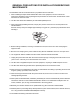
GENERAL PRECAUTIONS FOR INSTALLATION/SERVICING/ MAINTENANCE The installation and service shall be done by a qualified service technician. 1. When installing the Paper Feed Pedestal KD-1025 to the equipment, be sure to follow the instructions described in the "Unpacking/Set-Up Procedure for the KD-1025" booklet which comes with each unit of the KD-1025. 2. The KD-1025 should be installed by an authorized/qualified person. 3.
16.During servicing or maintenance work, be sure to check the nameplate and other cautionary labels (if any) to see if they are clean and firmly stuck. If not, take appropriate actions. 17.The PC board must be stored in an anti-electrostatic bag and handled carefully using a wristband, because the ICs on it may be damaged due to static electricity. Caution: Before using the wrist band, pull out the power cord plug of the equipment and make sure that there is no uninsulated objects in the vicinity. 18.
CONTENTS KD-1025 1. SPECIFICATIONS......................................................................................................... 1-1 2. OVERVIEW ................................................................................................................... 2-1 2.1 Front Sectional View............................................................................................................ 2-1 2.2 Layout of Electrical Parts ...................................................................
KD-1025 CONTENTS © 2009 - 2011 TOSHIBA TEC CORPORATION All rights reserved 2
1. SPECIFICATIONS 1 Item KD-1025 Appearance Feeding method Automatic feeding: 1 drawer installed from the front Paper Size: A3, B4, A4, A4-R, B5, B5-R, A5-R, LD, LG, LT, LT-R, 8K, 16K, 16K-R, FOLIO, COMPUTER, 13"LG, 8.5"x8.5" Thickness: 64 g/m2 to 105 g/m2 (17 lb. Bond to 94.5 lb. Cover) Capacity of drawer Stack height: 60.5 mm (Approx. 550 sheets: 80 g/m2 (22 lb. Bond)) Dimensions 575 (W) × 583 (D) × 292 (H) mm 22.64 (W) × 22.95 (D) × 11.
KD-1025 SPECIFICATIONS © 2009 - 2011 TOSHIBA TEC CORPORATION All rights reserved 1-2
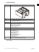
2. OVERVIEW 2.1 Front Sectional View 16 17 12 2 15 1 4 6 5 3 8 7 10 9 13 14 11 20 21 22 18 24 28 27 26 19 23 25 Fig.
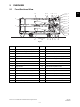
2.2 Layout of Electrical Parts Front side S10 CLT2 S8 S6 S4 S7 PWB S5 M1 S2 S3 Rear side S1 S11 S9 CLT3 M2 CLT1 M3 Fig.
2.3 Electrical Parts 1. Motor Symbol Name Function Remarks M1 PFP-MTR PFP motor Drives feeding and transport Brushless motor M2 T-UP-U-MTR Upper drawer tray-up motor Lifts up the upper drawer tray Brush motor M3 T-UP-L-MTR Lower drawer tray-up motor Lifts up the lower drawer tray Brush motor 2 2.
KD-1025 OVERVIEW © 2009 - 2011 TOSHIBA TEC CORPORATION All rights reserved 2-4
3. GENERAL OPERATION 3.1 Driving System and Feeding Operation The Paper Feed Pedestal (PFP) mainly consists of the drawer, pickup roller, feed roller, separation roller, transport roller, and drive systems for these components. • Feeding/Transport system The PFP motor drives the pickup roller, feed roller, and transport roller which are located in the feeding area. • Drawer tray system This system raises and lowers the tray.
3.2 Description of Operations [A] From power ON to ready (1) When the equipment is turned ON, the power is also supplied to the feeder unit. And when the power is supplied, the feeder unit detects and judges the clock frequency output from the LGC board on the equipment to control transport speed of the unit. (2) After that, the tray-up motor (M2)/(M3) is turned ON to raise the corresponding tray.
3.3 Error Detection [A] Jam detection (1) Paper jams (E150), (E160) and (E300 to E360) occur in the following cases. • Feed sensor (S2)/(S3) is not turned ON within a specified period of time after the feeding is started. • The leading edge of the paper does not pass the feed sensor (S2)/(S3) in the transport path within a specified period of time. (2) Open the side cover of the PFP and remove all the paper remaining on the transport path and close the side cover to clear the paper jam.
3.4 Flow Chart (Upper drawer feeding) Press [START] Transport system control Feed/transport motor ON Exit motor ON PFP motor ON PFP motor rotating normally? NO YES Call for Service "C040" Upper drawer feed clutch ON PFP Upper drawer feed sensor ON? NO Paper jam YES "E150" PFP transport clutch ON Upper drawer feed clutch OFF Copier’s 2nd drawer feed sensor ON? NO YES Paper jam Copier’s transport clutch ON B "E320" A Fig.
B A Copier’s 1st drawer feed sensor ON? NO 3 Paper jam YES "E310" NO Copier’s registration sensor ON? Paper jam YES "E300" Copier’s registration clutch ON Counter ON/OFF Copier’s transport clutch OFF PFP transport clutch OFF Copier’s registration clutch OFF Copier’s exit sensor ON? NO Paper jam "E010" YES Copier’s exit sensor OFF? NO Paper jam "E020" YES NO Remaining number of copies = 0? YES Feed/transport motor OFF Exit motor OFF PFP motor OFF Ready Fig.
KD-1025 GENERAL OPERATION © 2009 - 2011 TOSHIBA TEC CORPORATION All rights reserved 3-6
4. 4.1 DISASSEMBLY AND REPLACEMENT Installation and Removal of Drawers and Covers [A] Drawers (1) (2) Pull out the drawer fully and remove 1 screw at the back right to remove the stopper. Pull out the drawer further and take it out. 4 Stopper Fig. 4-1 [B] Drawer cover (1) (2) Take out the drawer. P.4-1 "[A] Drawers" Remove 4 screws and take off the drawer cover. Fig.
[C] Stabilizer cover (1) Take out the drawer. P.4-1 "[A] Drawers" Note: The drawer must be taken out only when taking off the front side stabilizer cover. (2) (3) Remove 2 screws and take off the front side stabilizer cover. Remove 1 screw and take off the feeding side stabilizer foot. Feeding side stabilizer foot Front side stabilizer cover Fig. 4-3 (4) Remove 2 screws and take off the rear side stabilizer cover. Rear side stabilizer cover Fig.
[E] Feeding side front cover (1) (2) Take out the drawer. P.4-1 "[A] Drawers" Remove 2 screws and take off the feeding side front cover. 4 Fig. 4-6 [F] Feeding side rear cover (1) (2) Open the side cover. Remove 2 screws, and take off the feeding side stabilizer foot and the feeding side rear cover. Feeding side rear cover Feeding side stabilizer foot Fig. 4-7 [G] Side cover (1) Open the side cover and remove 1 screw on the belt. Belt Fig.
(2) (3) Take off the block from the side cover. Take off the side cover while pushing the front side of the side cover inward. Block Fig. 4-9 (4) Disconnect 1 connector. Connector Fig.
4.2 (1) (2) PFP board (PWB) Take off the rear cover. P.4-2 "[D] Rear cover" Disconnect 6 connectors, remove 2 screws, and release 2 locking supports to take off the PFP board. Locking supports Screws 4 PFP board Fig.
4.3 Upper/Lower Transport Rollers [A] Upper transport roller (1) (2) Open the side cover and remove 1 screw on the belt. P.4-3 "[G] Side cover" Remove 3 screws and take off the transport roller along with the bracket. Bracket Fig. 4-12 (3) Remove 1 clip, and take off the gear and the collar. Collar Gear Clip Fig. 4-13 (4) Remove 1 clip and slide the bushing to take off the transport roller. Transport rollers Bushing Clip Bushing Fig.
[B] Lower transport roller (1) (2) Take off the rear cover. P.4-2 "[D] Rear cover" Loosen 1 screw fixing the tensioner bracket. 4 Fig. 4-15 (3) Remove the belt. Fig. 4-16 Note: When installing the belt, be sure to confirm the gap between the belts with the following procedure. Approx.3mm 1. Install the belt in KD-1025. 2. Tighten 1 fixing screw of the tensioner bracket. 3. Confirm that the gap between the belts is approx. 3 mm. Fixing screw Fig.
(4) Remove 2 screws and take off the bracket of the feeding gear. Fig. 4-18 (5) Remove 1 connector and take off the transport clutch. Transport clutch Connector Fig. 4-19 (6) Remove the coupling, pin, and clip. Coupling Pin Clip Fig.
(7) (8) Take off the side cover and the feeding side front cover. P.4-3 "[G] Side cover" P.4-3 "[E] Feeding side front cover" Remove 3 screws and take off the transport roller along with the bracket. Bracket 4 Fig. 4-21 (9) Remove 1 clip, and take off the gear and the collar. Collar Gear Clip Fig. 4-22 (10) Remove 1 clip and slide the bushing to take off the transport roller. Transport rollers Bushing Clip Bushing Fig.
4.4 Motor [A] Upper drawer tray-up motor (1) (2) Take off the rear cover. P.4-2 "[D] Rear cover" Disconnect 1 connector and take off the harness clamp from the bracket. Fig. 4-24 (3) Remove 2 screws and take off the tray-up motor along with the bracket. Bracket Fig. 4-25 (4) Remove 2 screws and take off the tray-up motor from the bracket. Tray-up motor Fig.
[B] Lower drawer tray-up motor (1) (2) Take off the rear cover. P.4-2 "[D] Rear cover" Loosen 1 screw fixing the tensioner bracket. 4 Fig. 4-27 (3) Remove the belt. Fig. 4-28 Note: When installing the belt, be sure to confirm the gap between the belts with the following procedure. Approx.3mm 1. Install the belt in KD-1025. 2. Tighten 1 fixing screw of the tensioner bracket. 3. Confirm that the gap between the belts is approx. 3 mm. Fixing screw Fig.
(4) Remove 2 screws and take off the bracket of the feeding gear. Note: Match the protruding portion of the clutch with the position shown in the figure for assembling. Protrusion Fig. 4-30 (5) Disconnect the connector of the lower drawer tray-up motor and remove 2 harness clamps from the bracket. Fig. 4-31 (6) Remove 2 screws and take off the tray-up motor along with the bracket. Bracket Fig.
(7) Remove 2 screws and take off the tray-up motor from the bracket. Tray-up motor 4 Fig. 4-33 [C] PFP motor (1) (2) (3) Take off the rear cover. P.4-2 "[D] Rear cover" Disconnect 1 connector. Remove 4 screws and take off the PFP motor. Connector PFP motor Fig. 4-34 [D] PFP motor assembly (1) (2) Take off the rear cover. P.4-2 "[D] Rear cover" Loosen 1 screw fixing the tensioner bracket. Fig.
(3) Remove the belt. Fig. 4-36 Note: When installing the belt, be sure to confirm the gap between the belts with the following procedure. Approx.3mm 1. Install the belt in KD-1025. 2. Tighten 1 fixing screw of the tensioner bracket. 3. Confirm that the gap between the belts is approx. 3 mm. Fixing screw Fig. 4-37 (4) Remove 1 connector and take off the PFP motor assembly. Connector PFP motor assembly Fig.
4.5 Feed/Separation/Pickup Roller [A] Drawer feeding unit (1) (2) Pull out the drawer for which the drawer feeding unit will be taken off and the drawer immediately above. P.4-1 "[A] Drawers" Remove 1 screw and pull the drawer feeding unit toward the inside of the copier. Upper drawer feeding unit 4 Lower drawer feeding unit Fig. 4-39 [B] Separation roller (1) (2) Take off the drawer feeding unit. P.4-15 "[A] Drawer feeding unit" Remove 1 screw and take off the separation roller holder. Fig.
(4) Remove the cover, the arbor, and the clutch spring from the shaft, and then take off the separation roller. Separation roller Clutch spring Arbor Shaft Cover Arbor Fig. 4-42 [C] Feed roller (1) (2) (3) Take off the drawer feeding unit. P.4-15 "[A] Drawer feeding unit" Take off the separation roller holder. P.4-15 "[B] Separation roller" Remove the clip and take off the feed roller. Feed roller Clip Fig. 4-43 [D] Pickup roller (1) (2) (3) Take off the drawer feeding unit. P.
(4) Remove pulley, one-way clutch, and 3 Erings to take off the pickup roller. Pulley One-way clutch Pickup roller E-rings 4 Fig. 4-45 [E] Drawer feed clutch (CLT2/CLT3) (1) (2) Take off the drawer feeding unit. P.4-15 "[A] Drawer feeding unit" Remove 2 screws, and take off the clutch bracket and the bushing. Bushing Clutch bracket Fig. 4-46 (3) Remove 1 connector and take off the clutch. Note: Match the protruding portion of the clutch with the position shown in the figure for assembling.
4.6 Switches and Sensors [A] Tray-up sensor (S4/S5)/paper empty sensor (S6/S7) (1) (2) Take off the drawer feeding unit. P.4-15 "[A] Drawer feeding unit" Remove 1 screw and take off the front side cover. Front side cover Fig. 4-48 (3) (4) Disconnect the connector and release the latch to take off the tray-up sensor. Disconnect the connector and release the latch to take off the empty sensor. Empty sensor Tray-up sensor Fig.
[C] Upper/lower drawer feed sensor (S2/S3) (1) (2) Take off the side cover. P.4-3 "[G] Side cover" Remove 6 screws and take off the guide. 4 Guide Fig. 4-51 (3) (4) Disconnect 1 connector. Release the latches and take off the sensor. Upper drawer feed sensor Latches Lower drawer feed sensor Fig. 4-52 [D] Side cover open/close switch (S1) (1) (2) Take off the side cover. P.4-3 "[G] Side cover" Remove 6 screws and take off the guide. Guide Fig.
(3) (4) Release the latches and take off the switch. Disconnect the connector. Side cover open/close switch Latches Fig. 4-54 [E] Upper/lower drawer detection switches (S8/S9) (1) (2) (3) (4) (5) Take out the drawer. P.4-1 "[A] Drawers" Take off the rear cover. P.4-2 "[D] Rear cover" Take off the PFP motor assembly. P.4-13 "[D] PFP motor assembly" Disconnect the connectors connected to the drawer detection switch. Release the latches and remove the switch from the front side.
5. ELECTRIC CIRCUIT 5.
5.2 Circuit Diagram Fig.
5 Fig.
Equipment upper drawer empty sensor upper drawer feed clutch upper drawer tray-up sensor upper drawer detection switch upper drawer paper stock sensor 5-4 upper drawer tray-up motor unit lower drawer tray-up motor unit lower drawerempty sensor lower drawerfeed clutch lower drawertray-up sensor lower drawerdetection switch lower drawerpaper stock sensor © 2009 - 2011 TOSHIBA TEC CORPORATION All rights reserved KD-1025 ELECTRIC CIRCUIT transport clutch PFP motor lower drawerfeed sensor upper
5.3 PC Board 5 Fig.
KD-1025 ELECTRIC CIRCUIT © 2009 - 2011 TOSHIBA TEC CORPORATION All rights reserved 5-6
6. PERIODIC MAINTENANCE 1 2 3 2 3 6 1 Fig. 6-1 Symbols used in the checklist Cleaning A: Clean with alcohol O: Clean with soft pad, cloth or vacuum cleaner Lubrication/Coating W1: W2: AV: L: White grease (Molykote EM-30L) White grease (Molykote HP-300) Alvania No.2 Launa 40 Replacement Operation check Value: Replacement cycle R: Replace if deformed or damaged O: After cleaning or replacement, confirm there is no problem.
* c1. Separation roller Apply an even coat of grease (Alvania No.2) to all round the inside of the spring. When replacing the separation roller, apply adequate amount of white grease (Molykote HP-300) on the places of the holder shown in the figure (4 places). Separation roller Holder Apply grease on the inside entirely Lever Separation roller Fig. 6-3 Fig. 6-2 Note: Make sure that the grease does not adhere to the roller surface. Wipe it off with alcohol if adhered. * c2.
REVISION RECORD Ver.02 Page 5-1 Ver.02 <2011.12.15> Contents The TOSHIBA logo on the cover page has been changed. The copyright description on the back side of the cover page has been changed. The model name in "5.1 Harness Diagram" has been changed. Page 4-7 Ver.01 <2010.02.05> Contents “Note” and an illustration for installing the belt have been added. 4-11 4-14 5-1 “Note” and an illustration for installing the belt have been added. “Note” and an illustration for installing the belt have been added.
KD-1025 REVISION RECORD © 2009 - 2011 TOSHIBA TEC CORPORATION All rights reserved 2