
User's Manual


© 2009 - 2011 TOSHIBA TEC CORPORATION All rights reserved KD-1025
CONTENTS
1
CONTENTS
KD-1025
1. SPECIFICATIONS......................................................................................................... 1-1
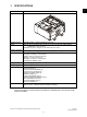
2. OVERVIEW ................................................................................................................... 2-1
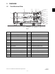
2.1 Front Sectional View............................................................................................................ 2-1
2.2 Layout of Electrical Parts ..................................................................................................... 2-2
2.3 Electrical Parts..................................................................................................................... 2-3
3. GENERAL OPERATION............................................................................................... 3-1
3.1 Driving System and Feeding Operation............................................................................... 3-1
3.2 Description of Operations ....................................................................................................3-2
3.3 Error Detection..................................................................................................................... 3-3
3.4 Flow Chart ........................................................................................................................... 3-4
4. DISASSEMBLY AND REPLACEMENT........................................................................ 4-1
4.1 Installation and Removal of Drawers and Covers................................................................ 4-1
4.2 PFP board (PWB) ................................................................................................................ 4-5
4.3 Upper/Lower Transport Rollers............................................................................................ 4-6
4.4 Motor ................................................................................................................................. 4-10
4.5 Feed/Separation/Pickup Roller .......................................................................................... 4-15
4.6 Switches and Sensors ....................................................................................................... 4-18
5. ELECTRIC CIRCUIT ..................................................................................................... 5-1
5.1 Harness Diagram................................................................................................................. 5-1
5.2 Circuit Diagram .................................................................................................................... 5-2
5.3 PC Board ............................................................................................................................. 5-5
6. PERIODIC MAINTENANCE.......................................................................................... 6-1