TOSHIBA AMERICA INFORMATION SYSTEMS STORAGE DEVICE DIVISION IRVINE, CALIFORNIA SD-R5372 DVD REWRITEABLE DRIVE USER MANUAL
CONTENTS Introduction..............................................................................1 Setup ........................................................................................3 Using the DVD Rewriteable Drive ...........................................7 Troubleshooting.....................................................................10 Specifications ........................................................................11 Drive Connectors.............................................
INTRODUCTION – SD-R5372 General Features Reads and records digital data on DVD-R/-RW, DVD+R/+RW, DVD+R DL, CD-R/-RW, HS CD-RW and US CD-RW discs.
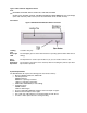
Types of Disc Formats Supported - Read DVD: DVD-ROM, DVD-R/RW, DVD+R, DVD+R DL, DVD+RW, DVD-RAM CD: CD-DA, CD+G, CD-MIDI, CD-TEXT, CD-ROM, CD-ROM XA, MIXED MODE CD, CD-I, CD-I Bridge (Photo-CD, Video-CD), Multi-session (Photo-CD, CD-EXTRA, CD-R, CD-RW, Portfolio) Front Panel Figure 1.SD-R5372 DVD Writeable Drive Front Panel Loading Tray Busy Light LED Load disc using tray. Eject Button Emergency Eject Hole The Eject button is used to open the disc tray so you can install or remove a disc.
SETUP – SD-R5372 The following steps must be performed to properly install your drive: • Set Drive Jumper Settings • Connect Audio Cable • Attach IDE BUS Cable • Attach Power Cable • Mount Drive Jumper Settings The mode select jumpers are 6 straight angle pins located on the rear of the DVD Rewriteable drive.
Placing DVD Rewriteable Drive inside your Computer Now that you have set the jumpers, you are ready to install your DVD Rewriteable drive inside your computer. Important Note: Disconnect power from your computer system before beginning installation. Remove computer cover and faceplate if required. Refer to your computer systems manual for removal information. If the DVD Rewriteable drive is replacing a CD-ROM or DVD-ROM, remove drive presently installed in your system.
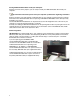
Power Cable - Connect an internal computer power supply cable to the power socket at the back of the DVD Rewriteable drive. One side of the plug has chamfered edges, so the power connector fits only one way. Push plug completely into the socket making sure the plug fits correctly. Figure 4.Installing Power Cable Audio Cable (optional) - If you have a sound card and speakers, and would like to play audio CDs on your computer, you will need to install a CD/DVD audio cable.
Software Driver - Toshiba's optical drives do not require any unique device drivers for Windows '95/'98/2000/Me/XP/NT. After installing your drive and re-booting, your system should recognize your drive. Windows '95/'98/2000/Me/XP/NT Operating Systems support all Toshiba optical drives natively If you prefer using DOS, download the DOS ATAPI driver from our web site. Other Software - Additional software is required to use the SD-R5372 CD-R/-RW, DVD-R/-RW and DVD functions.
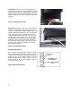
USING THE DVD REWRITEABLE DRIVE – SD-R5372 Drive Operation Inserting a Disc - Horizontally To insert a disc into a drive that is mounted horizontally, perform the following steps: Figure 1.Inserting Disc 1. Open the drive's Loading tray by pressing the Eject Button. 2. Place disc or into drive's Loading tray 3. Press Eject button again or gently push on the open disc tray. Tray will automatically close.
Figure 2.Inserting Disc Vertically Removing a Disc To remove a disc from the DVD Rewriteable drive, perform the following steps: 1. Open the Loading Tray by pressing the Eject Button. 2. Slide disc holders away from disc. 3. Grasp disc by edges, and lift out of loading tray. 4. Press Eject Button again to close Loading Tray. Software When you purchase the SD-R5372 as a Kit, it will include Nero6 OEM Suite Software.
NOTE: High-speed drives spin the disc at a high rotational speed. If a disc has printing on only half of the disc, or if there is a slight imbalance in the disc, the imbalance is greatly magnified by the high speed, causing the drive to vibrate or produce a fan-like noise. These effects are inherent in the high-speed technology and do not indicate a problem with the drive.
TROUBLESHOOTING – SD-R5372 Solution Problem Disc tray cannot be opened • • Check that there is power to drive. Use Emergency Eject instructions to open tray. Drive is not recognized by system • Is the drive connected properly? Are all cables plugged in properly (e.g. Power Cable, Interface Cable and Audio Cables).
SPECIFICATIONS –SD-R5372 General Interface: ATAPI Applicable Write Format CD-R/-RW Disc at once, Track at once, Session at once, Packet write DVD-R Disc at once, Incremental write DVD-RW Disc at once, Incremental write, Restricted overwrite DVD+R Sequential Write DVD+RW Sequential Write, Random Write Applicable Write disc DVD-R, DVD-RW, DVD+R, DVD+R DL, DVD+RW, CD-R, CD-RW, High Speed CD-RW, Ultra Speed CD-RW Applicable Formats - Read: DVD-ROM, DVD-R/RW, DVD+R, DVD+RDL, DVD+RW, DVD-RAM, CD-DA, CD+G, CD-MI
Performance Rotational Speed DVD-ROM (single layer) DVD-ROM (dual layer) DVD-R, DVD+R (read) DVD-RW, DVD+RW (read) DVD-RAM (Ver 2.1) (read) DVD-R (Ver 2.0) (Write) DVD-RW (Write) DVD+R (Write) DVD+RW (Write) CD-ROM, CD-R CD-DA Transfer CD-DA, Video-CD CD-RW (read) CD-R (write) CD-RW(write) High Speed CD-RW (Write) Ultra Speed CD-RW (Write) 9,200rpm (6.
Data Buffer 2MB Reliability MTBF 100,000 hours Power ON Hours ON/OFF Cycles Number of Access Operating Duty Cycle MTTR 5,436 hours/year 313 cycles/year 600,000 accesses/year 20% of Power ON time (Reading/Seeking) 2% of Power ON time (Writing/Seeking) 0.
Connectors DC input 4-pin Power Supply Connector ATAPI Interface Connector 40 Pin I/F ATAPI Standard Audio Connectors 4-pin and 2-pin connector (use matching housing, Part No. 70066, made by Molex Corp, or equivalent) Regulatory The SD-R5372 DVD Writeable drive has been certified by the following regulatory agencies: 14 • UL 1950 • CSA C22.2 No.
DRIVE CONNECTORS –SD-R5372 Figure 1.SD-R5372 DVD Rewriteable Drive Rear Panel - Connectors Power Connector Power is supplied to your DVD drive by the connection with your computer's +5V/+12V power cable to the power socket at the back of drive. One side of the plug has chamfered edges, so the power connector fits only one way. CAUTION: Severe damage to the Drive circuits may occur if power cable is plugged in upside-down with power ON.
Table 1.Interface Pin Assignments INTERFACE PIN ASSIGNMENT PIN NO. 1 2 3 4 5 I/O I I/O I/O I/O SIGNAL NAME Reset GND HD7 HD8 HD6 6 7 I/O I/O 8 9 10 11 12 13 14 15 16 17 18 19 20 16 HOST SIGNAL NAME I/O Host Data Bus BIT 7 Host Data Bus BIT 8 Host Data Bus BIT 6 PIN NO.