
Product Manual
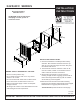


1. For surface mounting attach 3420/AFC box to wall.
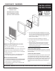
For semi-recessed mounting 3420AFC box should be
set in the wall so the flange is out from the finished
wall a distance equal to the frame depth (1” for a 1”
frame, 2” for a 2” frame).
2. Remove knockout(s) in 3420/AFC as required.
3. Proceed as with recessed installation described on
front - steps 2 & 3.
4. Extender frame is attached to heater front (slip fit)
and this assembly is then attached to the heater
following step 4 on front. Frame is captured between
heater front and finished wall.
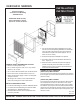
THERMAL CUTOUT OPERATION
(ZERO-VOLT) LIMIT CONTROL
To reset thermal cutout disconnect all power for 5 minutes
than energize unit. If fault continues disconnect power and
check for cause.
(CAPILLARY) LIMIT CONTROL
To reset thermal cutout disconnect all power, when heater
has cooled locate the two 1/4” dia. holes in the control
panel portion of the front grille. Using a small screwdriver or
pencil press the reset button (with minimal amount of force)
through the 1/4” dia. opening, then restore power to the
unit. If fault continues disconnect power and check for
cause.
Form 9282
ATTENTION: Read carefully
before attempting to install,
operate or service the heater.
3420/AFC SERIES
Surface Mounting
Semi-Recessed Mounting
3420/AFC Series
GENERAL SAFETY INFORMATION / CAUTION:
• Mount in vertical position only.
• Do not install any closer than 12” to any vertical
surface or 12” to floor.
• Do not mount beneath towel racks or behind doors.
• Heater must have no obstructions in front of it.
• Make certain power supply is same as nameplate
voltage on heater.
• All wiring must conform to the National Electric
Code and existing local code requirements.
IMPORTANT: OWNER SHOULD RETAIN THESE INSTRUCTIONS FOR FUTURE REFERENCE
INSTALLATION
INSTRUCTIONS
INSTALLATION INSTRUCTIONS:
• For Surface Mounting use extener 3420/AFC EX34
• For Semi-Recessed Mounting use extender 3420/
AFC EX16 for 2”, or 3420/AFC EX8 for 1”
• Box 3420/AFC must be used in conjunciton with
accessory extender.