
Product Manual
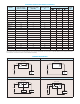

Model No.
AC Line Input Voltage
(Volts AC – 50/60 Hz)
Maximum Current Rating
(Amps RMS)
Ambient Temperature
(ºC)
Agency Approvals
Package
Type
KBWC-13 115 2.5 25
√ √
B
KBWC-15 115 5 40
√ √
C
KBWC-16 115 6 25
√
C
KBWC-18K
1
115 8 40
√ √
D
KBWC-110K
1
115 10 25
√ √
D
KBWC-110K
1
115 10 40
√ √
E
KBWC-112K
1
115 12 40 E
KBWC-115K
1
115 15 25
√
E
KBWC-23
2
230 2.5 25
√
B
KBWC-25
3
230 5 40
√
C
KBWC-26 230 6 25 C
KBWC-28K
1
230 8 40
√
D
KBWC-210K
1
230 10 40 E
KBWC-212K
1
230 12 40 E
KBWC-215K
1
230 15 25 E
KBWC-35 277 5 25
√
C
KBWC-36 277 6 25 C
KBWC-38K
1
277 8 25 D
KBWC-310K
1
277 10 25 D
KBWC-312K
1
277 12 25 E
KBWC-315K
1
277 15 25 E
Notes: 1. Models rated 8 Amps and above include Mounting Kit (suffix “K”). 2. Only model containing suffix “NS” is UL Recognized. 3. Only Model KBWC-25 (4L) is UL Recognized. 4. The maxi-
mum Locked Rotor current for UL listed controls is 6 times the Maximum Current Rating.
ELECTRICAL RATINGS AND AGENCY APPROVALS
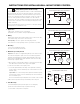
2-Wire Controls with On/Off Switch (Standard) 2-Wire Controls without On/Off Switch (Suffix “NS”)
LOAD
CONTROLLED
BLACK
SWITCH
TRIAC
BLACK
A
C LINE
SPEED CONTROL
TRIAC
CONTROLLED
LOAD
BLACK BLACK
SPEED CONTROL
A
C LINE
3-Wire Controls with Auxiliary Lead (Suffix “L”) 4-Wire Controls with DPDT On/Off Switch (Suffix “4L”)
WHITE
CONTROLLED
TRIAC
SWITCH*
RED
AUXILIARY
LOAD
BLACK
LOAD
*DO NOT EXCEED CURRENT RATING OF SWITCH
SPEED CONTROL
A
C LINE
CONTROLLED
LOAD
BLACK
SWITCH
RED
TRIAC
RED
BLACK
A
C LINE
SPEED CONTROL
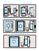
CONNECTION DIAGRAMS