IN-27000_B Installation Instructions Manual de Instrucciones Instructions d’installation TracRac Inc. 994 Jefferson St. FallRiver MA 02721 www.tracrac.com 800-501-1587 TracRac Inc. 994 Jefferson St.
10 4 4 10 4 4 9 10 00-27000-01/QTY. 4 DESCRIPTION 4 PART NUMBER 4 ITEM NO.
TracONETM T hank you for your purchase of a TracONETM cargo rack from TracRac®. TracRac® takes great pride in the quality and workmanship we put into every product. We designed the TracONE specifically to meet your cargo management needs and it will do just that. With 800 lbs of load capacity and its heavy-duty aluminum construction you can be sure this rack can handle all of your gear.
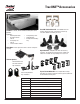
TracONETM Accessories TracBox - Full size, Silver Powder Coated, Crossover Toolbox. Features: • • • • Weatherproof Seals Dual Push Button Shocks Heavy Duty Gas Shocks L: 70 in. W: 20 in. H 20 in. • • • TracONE Toolbox Mount Kit - The toolbox mount kit includes Aluminum Shims & Hardware to mount any crossover toolbox that will fit your truck. 2 Stage Rotary Latch Foam Filled Lid 5 Compartment Sliding Tray Bike Mount - mount your bikes to the crossbar safely and securely.
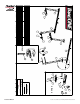
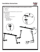
Installation Instructions These instructions will guide you through the 3 main component assemblies: 1. Upright units 2. Cross bars 3. Clamp units Please reference the drawing below for a general overview. Tool you will need: • 3/16” Allen Key • 7/32” Allen Key • Tape Measure • 9/16” Socket and Socket Wrench • Recommended: Torque Wrench 7/32” Allen Drive Bit Non-Impact Drill B A TracRac Inc. 994 Jefferson St.
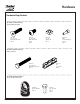
Hardware Hardware Bag Contents 01-27016 Hardware Bag-1 Upright/Saddle Hardware Item # 12 3/8 - 16 x 1.5” Flat Head Cap Screw Qty - 16 Item # 13 3/8 - 16 x .625” Button Head Cap Screw Qty - 8 Item # 14 3/8 - 16 Square Nut Qty - 8 Item # 15 M6-1 Socket Head Cap Screw Qty - 4 01-27015 Hardware Bag-2 Clamp Hardware Item # 18 3/8 - 16 x 2.5” Hex Head Cap Screw Qty - 8 Item # 19 3.
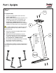
Part 1 - Uprights Step 1 12 1.1 Upright Assembly 1. First take the upright (Item 4) and insert it into a modular saddle (Item 3). 2. Bolt the saddle through the top by using two 3/8”-16 flat head cap screws (Item 12) and tighten using an 7/32” Allen Wrench (or 7/32” Allen Drive Bit). Torque the 3/8” -16 FHCS to 32 ft-lbs. We recommend threading both flat head cap screw initially by hand to ensure that you don’t cross thread the bolt. 1.1.
Part 2 - Cross Bars Step 2 20 2.1 Crossbar Assembly 1. Take the double T-Slot crossbar (Item 1) and insert four square nuts (Item 14) into the bottom T-Slot. Reference Figure 2.1, 2.2 & 2.3 2. Insert a T-bolt (Item 21) through the bottom of the cross bar tie-down (Item 20) and slide the unit into the top track of the crossbar so that both the bolt and the tiedown are locked into the t-track. 3. Insert the Crossbar End Cap with the flat mounting surface facing down into the end of the crossbar.
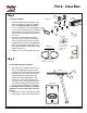
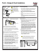
Part 3 - Clamps & Truck Installation Step 4 7 19 4.1.2 We recommend that you apply Loc-Tite (red) to any thread that is engaged with the clamp. 4.1.3 HHCS (Item 18) should be re-torqued every 5000 miles. Apply Loc-Tite within this area 4.1 Base Clamp Assembly 1. Take a modular clamp (Item 7) and thread a 3/8”-16 hex head cap screw (Item 18) through the bottom as shown. (See note about Loc-Tite) 2. Now take a C channel clamp foot (Item 19) and place it on top of the 3/8” hex head cap screw as shown. 3.
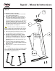
Español - Manual de Instrucciones Paso 1 12 1.1 Montaje de las barras verticales 1. Primero tome la barra vertical (ítem 4) e insértela en un soporte modular (ítem 3). 2. Atornille el soporte desde la parte superior con dos tornillos de cabeza plana de 3/8”-16 (ítem 12) y ajústelos con la llave Allen de 7/32” (ítem 16) y una llave de tubo con conector de 1/4”. Apriete con firmeza los tornillos de cabeza plana de 3/8”- 16 a 32 libras-pie.
Español - Manual de Instrucciones Paso 2 20 2.1 Montaje de la barra transversal 1. Tome la barra transversal con doble ranura en T (ítem 1) e inserte cuatro tuercas cuadradas (ítem 14) en la ranura en T inferior. Consulte las Figuras 2.1, 2.2 y 2.3. 2. 2. Inserte un perno en T (ítem 21) desde la parte inferior del anclaje de la barra transversal (ítem 20) y deslice la unidad en la guía superior de la barra transversal, para que tanto el perno como el anclaje queden fijados en la guía en t. 3. 3.
Español - Manual de Instrucciones Paso 4 7 19 4.1.3 Deberá volver a apretar con firmeza los tornillos de cabeza hexagonal (ítem 18) cada 5000 millas. 18 4.1.2 Recomendamos que aplique Loc-Tite (rojo) en todas las roscas que estén engrandas con la abrazadera. Step 5 5.1.1 Nota: Asegúrese de que las cuñas de goma estén debajo de la base cuando 4.1 Montaje de la abrazadera base 1.
Français - Instructions d’installation 1ère Partie - Montants Étape 1 12 1.1 Upright Assembly 1.1 Assemblage du montant 1. 1. Prenez d’abord le montant (pièce 4) et insérez-le dans un sabot modulaire (pièce 3). 2. 2. Boulonnez le sabot par le haut au moyen de deux vis d’assemblage à tête plate de 3/8 -16 po (pièce 12) et serrez l’ensemble au moyen de la clé Allen de 7/32 po et une douille de 1/4 po. Serrez les 16 FHCS de 3/8 po à 32 pi/lb.
2e Partie - Barres transversales Étape 2 2.1 Assemblage des Barres transversales 1. Prenez la barre transversale à double rainure en T (pièce 1) et insérez quatre écrous carrés (pièce 14) dans la rainure en T inférieure. Reportez-vous aux figures 2.1, 2.2 et 2.3 2.
3e Partie - Installation des étriers de fixation sur la camionnette Étape 4 7 19 4.1.2 Nous recommandons l’application de LocTite (rouge) sur le filetage traversant l’étrier. 4.1.3 Les HHCS (pièce 18) doivent être resserrés tous les 5000 miles. Apply Loc-Tite within this area 4.1 Assemblage des étriers sur la base 1. 1. Prenez un étrier de fixation (pièce 7) et vissez une vis d’assemblage à tête hexagonale 3/8 po -16 (pièce 18) à travers la partie inférieure comme indiqué.
TracRac® Limited Lifetime Warranty TracRac® Limited Lifetime Warranty TracRac® Incorporated will warranty all TracRac® truck and van racks manufactured by TracRac® Incorporated during the time that an original retail purchaser owns the product. TracRac® will warranty all other accessories for a period of 2 years from the date of purchase. This warranty terminates if a purchaser transfers the product to any other person.
PRODUCT REGISTRATION CARD By completing (the form on the next page or on tracrac.com) and returning your PRODUCT REGISTRATION CARD you will receive these important benefits: WARRANTY CONFIRMATION: Your prompt product registration confirms your right to the protection available under terms and conditions of your TracRac warranty. PRODUCT PROTECTION: We will keep the model number and date of purchase of your TracRac product on file to help refer to this information in the event of a product warranty issue.
14 Where do you plan to use this product? 21 Marital status: 15 Who made the decision to purchase this prod- 22 Including yourself, how many people in your 1. q Work 2. q Home uct? 3. q Other 1. q Yourself only 2. q Work initiated 3. q Someone else 16 What do you carry on your rack? 1. q Lumber 2. q Ladders 3. q Sports equipment 3. q Other 17 Do you have any suggestions as to how we can improve the product? ........................................................................................