
Manual

TracRac Inc. 994 Jefferson St. Fall River, MA 02721 l 800-501-1578
Instruction Manual
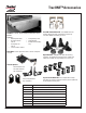
Part 2 - Cross Bars
Step 2
Step 3
Figure 3.1
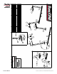
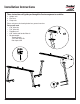
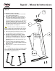
2.1 Crossbar Assembly
Take the double T-Slot crossbar (Item 1) and 1.
insert four square nuts (Item 14) into the bot-
tom T-Slot. Reference Figure 2.1, 2.2 & 2.3
Insert a T-bolt (Item 21) through the bottom of 2.
the cross bar tie-down (Item 20) and slide the
unit into the top track of the crossbar so that
both the bolt and the tiedown are locked into
the t-track.
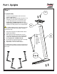
Insert the Crossbar End Cap with the flat 3.
mounting surface facing down into the end
of the crossbar. Using the clearance hole on
the bottom of the crossbar and the M6 SHCS
(Item 15). Tighten down the M6 SHCS using a
3/16” Allen Key. Repeat on the opposite side.
Reference Figure 3.1
Repeat steps 1-3 for the remaining crossbar.4.
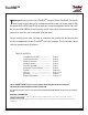
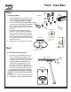
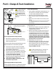
3.1 Front & Rear Crossbar Installation
Now place the assembled crossbar on top 1.
of the assembled uprights. Make sure the
crossbar is right side up. Reference Figure 2.3
Slide the Square Nuts (Item 14) so that they 2.
are directly above the slotted hole in the
saddle. Insert the 3/8 BHCS (Item 13) into
the Square Nuts (Item 14) and tighten the
cap screws, using an 7/32” Allen Wrench (or
7/32” Allen Drive Bit) Do not fully torque the
screws until Step 8 of the Truck Installation
3.1.1 Note: Make sure that the BHCS sits completely
within the recessed area of the saddle casting. See
Figure 3.2
Repeat Steps 1 and 2 for the opposite upright.3.
Repeat Steps 1-3 for the remaining crossbar. 4.
2.4.1 t h i s f a c e d o w n
2.2.1 no t e : f l at
f a c e o f t h e s q u a r e
n u t m u s t f a c e t h e
o p e n s l o t o f t h e
c h a n n e l
Figure 2.2
Crossbar End View
Top
Bottom
2.3.1 g r o v e f i t s i n t o s a d d l e
Figure 2.3
Figure 2.4
13
14
21
20
2
15
2
15
Figure 3.2
Figure 2.1
1