***ATTENTION*** PLEASE REMOVE THE RIGHT SIDE BAFFLE FILTER TO LOCATE YOUR NEW REMOTE CONTROL.
Revised 08/01/2018 Copyright © 2018 Trade-Wind Manufacturing, LLC Proverbs 22:29 Page 2
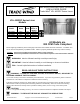
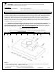
INSTALLATION INSTRUCTIONS & USE & CARE GUIDE ` Trade-Wind® VSL 4002RC Series Liners VSL 4002RC Series Liner Models Model Width CFM Type of Motor & Blower VSL4302RC VSL4362RC VSL4422RC VSL4482RC 28 /8” 3 34 /8” 3 40 /8” 3 46 /8” 3 290 290 290 290 Internal Internal Internal Internal All Models are 300 CFM Code Compliant Before beginning installation, please thoroughly read and become familiar with these instructions. Installation and service must be completed by a qualified installer.
a) Never leave surface units unattended at high settings. Boilovers cause smoking and greasy spillovers that may ignite. Heat oils slowly on low or medium settings. b) Always turn hood ON when cooking at high heat or when flambeing food (i.e. Crepes Suzette, Cherries Jubilee, Peppercorn Beef Flambe’). c) Clean ventilating fans frequently. Grease should not be allowed to accumulate on fan or filter. d) Use proper pan size. Always use cookware appropriate for the size of the surface element.
CAUTION – To reduce the risk of fire and electric shock, install this (range hood) only with Remote Blower models rated maximum 6 amps. CONTENTS: Part 1 - Planning The Installation Part 3 - Use & Care PART 1 Part 2 - Securing The Liner Part 4 - Electrical Connection (Give copy of these 2 pages to electrician.) Planning the Installation ® Trade-Wind Designer Series Liners are designed for installation inside custom hood canopies.
PART 2 Securing the Liner TILE BACKSPLASHES 3 IMPORTANT: Liners installed immediately above the top edge of tile backsplashes thicker than /4” should be installed slightly forward—not flush with the back wall. The back filter bracket of the liner is 1” deep and tile installations thicker than this will prevent the filters from being removable. MOUNTING HOLES NOTE: DRILLING THROUGH STAINLESS STEEL REQUIRES A TITANIUM BIT. BE CAREFUL NOT TO DRILL THROUGH FILTER BRACKETS, ELECTRICAL COMPONENTS OR UL LABEL.
The filters may be cleaned by hand washing in hot water using a mild detergent solution, or by placing them in a dishwasher. Locate holes on the sides of the filter. Put filter in dishwasher with holes facing up so detergent can enter filters. Dry the filters completely before using again. Rinse and dry with a soft lint-free cloth. Always wipe stainless steel surfaces with the grain. Never wipe across the grain. After cleaning, reinstall the filters carefully.
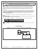
PART 4 Electrical Connection IMPORTANT: Copy this page for your electrical installer. WARNING! Ensure that the power supply is disconnected before proceeding. Verify that the power supply matches the ratings found on the appliance data label before proceeding. The complete appliance must be properly grounded at all times when electrical power is applied. Do not ground the appliance with the neutral (white) house supply wire. A separate ground wire must be utilized.
WARRANTY Kitchen Ventilation Products What IS Covered: ® ® Trade-Wind Manufacturing, LLC warrants its Trade-Wind Kitchen Ventilation Products to the original user, to be free of defects in materials and workmanship for three (3) years from the date of purchase. ® Trade-Wind Manufacturing, LLC at its option, will repair or replace the complete unit or any defective component without charge. This warranty may be voided if any unauthorized service, alterations, or repairs are made to the product.
Best Practices Venting Installation Instructions for Range Hoods and Wood Hood Liners (All Models) —Addendum to Installation Instructions— IMPORTANT: Problems caused by improper installations are not covered by the manufacturer’s warranty. 1. IMPORTANT: Undersized and improperly installed duct pipe and/or other ventilation components will cause excessive static pressure (air resistance), that may result in rattling, vibration and air buffeting noises, as well as inadequate ventilation.
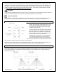
c. Duct runs for 290 and 390 CFM ventilator models should not exceed 20 linear feet with two 90degree elbows (or four 45-degree elbows), a damper and a roof or wall cap. Longer runs or additional elbows will result in decreased ventilation performance. Each 90-degree elbow is the equivalent of 8 linear feet of duct pipe; each 45-degree elbow is equivalent to 4 linear feet of duct pipe. d.
5. Roof Caps and Wall Caps The roof cap or wall cap is the termination point of the venting system that allows the exhaust air to exit to the outdoors. All sections of this fitting must have an equal or greater air path area than the ventilator’s discharge port. If any section of the roof cap or wall cap is smaller than the ventilator’s discharge port, the entire ventilation system will lose efficiency and the restriction will cause increased static pressure.