
Installation Instructions


Revised 08/01/2018 Copyright © 2018 Trade-Wind Manufacturing, LLC Proverbs 22:29 Page 11
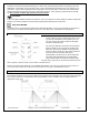
c. Duct runs for 290 and 390 CFM ventilator models should not exceed 20 linear feet with two 90-
degree elbows (or four 45-degree elbows), a damper and a roof or wall cap. Longer runs or additional
elbows will result in decreased ventilation performance. Each 90-degree elbow is the equivalent of 8
linear feet of duct pipe; each 45-degree elbow is equivalent to 4 linear feet of duct pipe.
d. Duct runs for 600 – 1200 CFM ventilator models should not exceed 35 linear feet with two 90-degree
elbows and two 45-degree elbows, a damper and a roof or wall cap. Longer runs or additional elbows
will result in decreased ventilation performance. Each 90-degree elbow is the equivalent of 6 linear
feet of duct pipe; each 45-degree elbow is equivalent to 3 linear feet of duct pipe.
e. Always run ventilator ducts to the outdoors. DO NOT terminate a duct into an attic, basement,
garage, crawl space under a house, a chimney, other ducting or an enclosed room.
4. Dampers
IMPORTANT: DO NOT USE SCREWS TO ATTACH ANY TYPE OF DAMPER AS THE SCREWS MAY BLOCK THE
DAMPER BLADES.
IMPORTANT: DO NOT USE MORE THAN ONE DAMPER IN THE VENTILATION SYSTEM. NOTE: Many styles of
roof caps and wall caps have built-in dampers. See Roof Caps and Wall Caps section for more detail.
Always use carefully crafted, tightly wrapped Aluminum Foil Metal Duct Tape on all connections and physically
view and test the damper blades to make certain they are opening and closing correctly. Make sure that the
damper blades do not touch the duct walls and that there is no debris blocking the free movement of the
damper mechanism. Common things to look for include screws protruding into the blade’s path, overspray of
paint, plaster and insulation. If using rectangular duct, be sure that all four sides of the duct are on the
outside of the damper’s start collar or frame.
a. 290 CFM Models
290 CFM models have a 6" start collar that may use a 6" damper (sold separately). DO NOT USE
SCREWS TO ATTACH THE DUCT TO THE DAMPER FRAME AS THE SCREWS MAY BLOCK THE DAMPER
BLADE. ALWAYS use Aluminum Foil Metal Duct Tape on all connections and physically view the
damper blade to make certain it is operating correctly. On ventilator installations designed to
recirculate the exhaust air back into the kitchen, be sure to remove the aluminum damper blade
before attaching the duct to the damper frame.
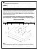
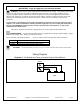
b. In-line dampers must be installed so that the exhaust air flow will open the butterfly blades.
For horizontal duct runs, the in-line damper must be installed so that the hinge between the two
butterfly blades is vertical—the hinge pin must point up and down. Otherwise, because of gravity,
the damper’s blades will not close and the damper will not prevent backdrafts.
For vertical duct runs, the in-line damper’s hinge will be horizontal (sideways), which is correct for
vertical duct runs. Gravity will help close the damper blades after each use.
For upward slanted duct runs, the in-line damper’s hinge must point to the top and bottom sides of
the duct. In his position, gravity will help close the damper blades after each use. Otherwise, because
of gravity, the damper’s blades will not close and the damper will not prevent backdrafts.