
Installation Instructions

Revised 08/01/2018 Copyright © 2018 Trade-Wind Manufacturing, LLC Proverbs 22:29 Page 6
PART 2 Securing the Liner
TILE BACKSPLASHES
IMPORTANT: Liners installed immediately above the top edge of tile backsplashes thicker than
3
/
4
” should be
installed slightly forward—not flush with the back wall. The back filter bracket of the liner is 1” deep and tile
installations thicker than this will prevent the filters from being removable.
MOUNTING HOLES
NOTE: DRILLING THROUGH STAINLESS STEEL REQUIRES A TITANIUM BIT. BE CAREFUL NOT TO DRILL
THROUGH FILTER BRACKETS, ELECTRICAL COMPONENTS OR UL LABEL.
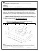
Because the Trade-Wind
®
Standard Series Liner was designed for various wood hood applications, no mounting
holes have been pre-drilled. This allows the liner to be attached in most any area of the canopy that has a wood
frame support, e.g., the back, sides or top. We recommend at least six equally spaced screws per liner—three
screws along the back (top or back side panel) and three screws on the front top, immediately next to the light bar
wall or behind the removable light bar. Where possible, the screw holes should be drilled into the top of the liner
(instead of the sides or back). This will help prevent distorting the liner walls in situations where the wood frame is
not properly sized to the liner. Models with internal motors should also have at least one screw centered and
securely in place on each end (side panel) of the liner because of the added weight.
Neatly measure and mark (left to right and top to bottom) and drill screw holes through the liner as required to
match the wood backing. It is easier to drill holes from the outside in, by setting the liner on its face (on cardboard)
and drilling from the back side. Secure the liner by driving screws (by others) tightly into the wood frame. Use
washers where necessary. When removing the filters, be careful not to scratch the liner by placing the filters,
screws, drill bits or drill on the liner’s face.
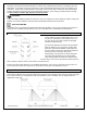
CONNECTING TO THE VENT PIPE
The VSL liner comes with a metal start collar welded in place. Attach the Start Collar to the duct with at least three
equally spaced screws. Also apply duct tape, preferably the metal type.
PART 3 Use and Care
WARNING! Do NOT operate the blower / ventilator system without the filters in place, or with dirty, grease
laden filters.
OPERATING CONTROLS:
Always activate the ventilator when using cooking appliances. For best performance, turn on the blower a few
minutes before starting to cook to establish an airflow pattern within the room. To use the electronic touch control,
touch the button that corresponds to the desired speed. To turn off blower, touch the illuminated speed button
again or the illuminated blower off control button. The electronic light control when touched comes on high, touch
again for light off.
ENERGY SAVING TIPS:
Eliminate air currents in the liner vicinity by shutting nearby windows and doors, turning off ceiling fans and
adjusting the adjacent heating and air conditioning outlets if necessary. Place your largest pans on the rear
burners whenever possible. Clean filters and grease laden surfaces often to improve efficiency. Always use lids on
cookware to retain heat and moisture. Minimize the amount of liquid used to cook food. Select cookware of proper
size, material and construction for the cooking task being performed.
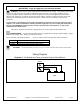
CARE & CLEANING:
Proper cleaning is necessary to maintain performance and appearance, while also ensuring safe operation. The
frequency of cleaning should be according to the type and amount of cooking. Best results will be achieved by
cleaning soiled components as soon as possible. Filters must be cleaned regularly. Using the aluminum knob,
lightly pull the filter toward the front of the liner while pulling the backside downwards. Replacing the filter is just as
easy as taking it out. For visual instructions on how to remove the filters visit our YouTube page
(https://www.youtube.com/channel/UCwVIbi_9hbuIATTYvz43oBA).