
Owner's manual


TM411N, TM412N,
TM413N, TM414N
Revised
7.11.13
10
45. Using the factory isolators install the sup-
plied front coil springs (24514 Gas or 24515
Diesel) into the spring buckets and raise the
axle into place. Make sure the coil spring
seats properly on the lower spring perch.
46. Install the new shocks (TM75880W).
Torque the upper mounting hardware to 46
ft. lbs. and the lower mounting hardware to
111 ft. lbs. Use thread locker on these bolts.
47. Install draglink end into pitman arm and
torque draglink nut to 148 ft. lbs. Reinstall
cotter pin.
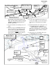
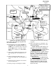
48. Install the sway bar drops (82-7026 drvr
and 82-7029 pass) to the OE sway bar
mounting studs on the frame using the previ-
ously removed OE hardware. See ILLUS-
TRATION 9.
49. Carefully raise the sway bar back into place
and on the passenger side insert the steering
stabilizer bracket (82-3823) under the pas-
senger side sway bar mount. On the driver
side insert the sway bar spacer plate (82-
3822) under the driver side sway bar mount.
Secure the supplied 7/16” X 1 3/4” bolts and
hardware. See ILLUSTRATION 9.
NOTE: Be sure the steering stabilizer
mounting hole in the stabilizer bracket is
oriented toward the rear of the vehicle.
50. Reattach the sway bar to the OE sway bar
end links using the previously removed OE
hardware.
51. Install the OE steering stabilizer to the new
steering stabilizer bracket (91-3823) using
the provided 12mm X 65mm bolt and hard-
ware. See ILLUSTRATION 9.
52. Torque all sway bar hardware according to
manufacturers specifications.
53. On the driver side, re clip the axle vent line
on the frame providing adequate slack for
the line at full droop.
54. On the passenger side, reposition the clip on
the axle hub vacuum line to provide ade-
quate slack to re-clip the line to the existing
hole on the outside of the bump stop plate.
NOTE: Be sure that the newly rerouted
vent line does not interfere with the travel of
the bump stop.
55. Remove the ABS line from the inner fender.
Drill a new hole, using a 15/64” bit, 3”
lower in the fender to provide adequate slack
for line and reattach the ABS line.
56. Reinstall the ABS wiring onto the radius
arms using the factory clips.
57. Refasten the lower brake line mount to the
lower coil spring perch using the OE hard-
ware.
58. Reinstall the front wheels and lower the ve-
hicle to the ground. Torque to manufactur-
ers specs.
59. Torque the OE rear Radius arm bolts to 222
ft. lbs.
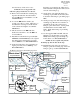
60. Reinstall the track bar into the Trailmaster
track bar bracket (82-9290) using the OE
bolt and adjustable cam plates (90-9295).
Torque to 406 ft. lbs. See ILLUSTRATION
3.
NOTE: You may find that having
someone inside the vehicle and moving the
steering wheel from side to side will aid in the
alignment of the track bar. DO NOT
start the
engine for this! You only have to move it
enough to line the holes up on the track bar
mount.
61. On both sides of the vehicle, check the
routing of the brake lines and the ABS wire
harnesses. There must be no pinching,
rubbing, or stretching of either component.
At full droop, cycle the steering from lock to
lock while observing the reaction of these
components. Reposition them if needed.
62. With the vehicle fully on the ground, meas-
ure the clearance between each
tire and in-
ner fender. If the axle is not properly cen-
tered, readjust the track bar cam hardware.
Torque to 406 ft.
NOTES:
On completion of the installation, have
the suspension and headlights re-aligned.
After 100 miles recheck for proper torque
on all newly installed hardware.
Recheck all hardware for tightness after
off road use.