
Owner's manual


TM411N, TM412N,
TM413N, TM414N
Revised
7.11.13
3
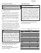
Before Starting Installation
1. Carefully read all warnings and instructions com-
pletely before beginning.
2. Verify all parts have been received in this kit by
checking the parts list at the end of this document.
3. Only install this kit on the vehicle for which it is
specified. If anytime during the installation you en-
counter something different from what is outlined in
the instructions, call technical support at (877) 695-
7812.
4. Park vehicle on a clean, dry, flat, level surface and
block tires so vehicle cannot roll in either direction.
5. Measure ride height with the vehicle supporting its
own weight on level ground. To settle the suspension,
the vehicle should be driven forward at least 10 feet
immediately prior to taking these measurements. Ride
height is the measurement from the center of the axle
straight up (vertical) to the fender lip. Record this
measurement for all four wheels.
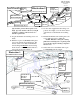
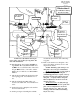
Engine Compartment
1. Disconnect both battery cables. Disconnect
negative cable first, then positive cable.
Wheel & Tire Requirements
The factory wheel and tire combination will fit
once this kit is installed.
Torque Specifications:
See factory service manual for torque values
when reusing OE fasteners.
NOTE
Kit parts are prefaced by the word kit and appear in
bold print.
NOTE
Adhere to recommendations when replacement fas-
teners, retainers and keepers are called out in the
factory service manual. When re-assembling the ve-
hicle it is recommended by the vehicle manufacturer
that certain fasteners are replaced in order to main-
tain proper retention characteristics. This system
may not include all replacement hardware as recom-
mended by the factory service manual. Additional
replacement hardware should be obtained prior to
installation of this system to meet the requirements
of the factory service manual.
See factory service manual for torque values when re-using
OE fasteners.
Bolt Size Grade 5 (ft.-lbs.) Grade 8 (ft.-lbs.)
1/4”-20 10 10
1/4”-28 10 12.5
5/16”-18 17 22.5
5/16”-24 20 25
3/8”-16 30 40
3/8”-24 35 45
7/16”-14 50 65
7/16”-20 55 70
1/2”-13 75 100
1/2”-20 80 115
9/16”-12 105 135
9/16”-18 115 150
5/8”-11 150 195
5/8”-18 160 210
3/4”-16 175 225
Tire & Wheel Information:
Due to differences in manufacturing, dimensions and
inflated measurements, tire and wheel combinations
should be test fit prior to installation. Tire and wheel
choice is crucial in assuring proper fit, performance,
and the safety of your Trailmaster equipped vehicle.
For this application, we recommend a wheel not to
exceed 10” in width with a maximum backspacing of
5 3/4” must be used. Additionally, a quality tire of
radial design, not exceeding 37” tall X 12.50” wide is
also recommended. Violation of these recommenda-
tions will not be endorsed as acceptable by Trailmas-
ter Suspension and will void any and all warranties
either written or implied.