Diagnostic Troubleshooting Repair Series R® 70-125 Ton Air-Cooled and Water-Cooled Rotary Liquid Chillers Model RTAA 70-125 Ton RTWA 70-125 Ton RTUA 70-125 Ton August 2005 © American Standard Inc.
NOTICE: Warnings and Cautions appear at appropriate sections throughout this literature. Read these carefully. WARNING: Indicates a potentially hazardous situation which, if not avoided, could result in death or serious injury. CAUTION: Indicates a potentially hazardous situation which, if not avoided, may result in minor or moderate injury. It may also be used to alert against unsafe practices. CAUTION: Indicates a situation that may result in equipment or propertydamage only accidents.
Contents General Information . . . . . . . . . . . . . . . . . . . . . . . . . . . . . . . . . . . . . . . . . . 4 Service Philosophy . . . . . . . . . . . . . . . . . . . . . . . . . . . . . . . . . . . . . . . . . . . . . . 4 System Description . . . . . . . . . . . . . . . . . . . . . . . . . . . . . . . . . . . . . . . . . . . . . . 5 System Level Components . . . . . . . . . . . . . . . . . . . . . . . . . . . . . . . . . . . . . . . . 5 Interprocessor Communications . . . . . . . . . . . . . . . . . .
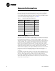
General Information The Unit Control Modules (UCMs) described in this troubleshooting guide provide a microprocessor based refrigeration control system, intended for use with Trane 70-125 ton helical rotor chillers. Six types of modules are used, and throughout this publication will be referred to by their abbreviations or their Line Wiring Drawing Designations, see Table 1. Table 1 Unit Control Module Designations Line Drawing Designation Controller Name Chiller Module Abbrev.
General Information System Description The CPM is the master module and coordinates operation of the entire system. One is used per chiller. The MCSP is a compressor protection module with one being used for each of the compressors in the chiller. The EXV is the expansion valve controller module which controls two Electronic Expansion Valves. There is one valve on each of the two refrigeration circuits. The CLD is a two line, 40 character alphanumeric interface to the system.
General Information High Pressure Cutout Switch Low Pressure Cutout Switch Variable Speed Fan Drive Motor Temperature Thermostats Slide Valve Load/Unload Solenoids Step Load Solenoid Valve Chiller Module (CPM) IU1 The CPM module performs machine (chiller) level control and protection functions. Only one CPM is present in the chiller control system.
General Information Real time data for temperatures, diagnostics and control algorithms etc. are made available to the CPM and the other modules for display and for input to higher level functions. See Electronic Expansion Valve Module (EXV) (1U3) on page 58 for details. Options Module (CSR) 1U2 The CSR module is an optional part of the system and employs communications circuits for interface to Trane Building Automation Systems, done through 1C17.
Interprocessor Communications The respective modules communicate with each other via an InterProcessor Communication link (IPC). The IPC allows the modules to work in a coordinated manner with the CPM directing overall chiller operation while each module handles specific subfunctions. This IPC link is integral and necessary to the operation of the Unit Controls and should not be confused with the Optional ICS (Integrated Comfort System) communication.
Interprocessor Communication from the Options Module. When some problem exists with the IPC link or a module fails, it is not uncommon for more than one of these IPC diagnostics to be displayed. Note that only those diagnostics that are indicated to be active currently exist. All other historic diagnostics should be disregarded for the purpose of the following troubleshooting discussion. See RTAA-IOM-4 for a complete listing of diagnostics.
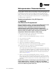
Interprocessor Communication * #,$ 5 * #0 5 * -3#0 " 5 * -3#0 ! 5 * %86 -!34%2 5 * * #32 5 /R ,#) # 5 * )0#" 5 2%-/4% #,$ 5 AND 5 ARE MUTUALLY EXCLUSIVE OPTIONS 4HE 2EMOTE #,$ IS NOT AVAILABLE IF THE 5 OPTION IS INSTALLED Figure 1 10 IPC Link Order For 70-125 Ton RTAA RLC-SVD03A-EN
Interprocessor Communication . Table 2 IPC Address Dip Switch (SW1) Settings for MCSP an EXV Modules MODULE DESIG. CONTROLLING MCSP “A” 1U4 COMPRESSOR A DIP SWITCH SETTING SW1-1 SW1-2 OFF OFF MCSP “B” 1U5 COMPRESSOR B OFF ON EXV 1U3 CKTS. 1 & 2 OFF OFF 3. Loss of power to a module: Generally a power loss to a particular module will only affect communications with that module. The module can usually be identified by analysis of the IPC diagnostics.
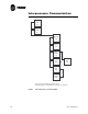
Interprocessor Communication - $03 F F KHDGHU SLQV RU HTXLY :LUH MXPSHUV VROGHUHG RU ZUDSSHG LQWR SLQV Figure 3 IPC Jumper For Bypassing Modules (to be inserted into MTA connector in place of module) 5. Improper connections to terminal J2: Jack J2, present on all modules except CLD, should have no connections. This input is for manufacturing test purposes only and any connections, shorts, etc.
Interprocessor Communication 3. Determine which modules are still talking. Wiring up to these is likely to be OK. 4. Try disconnecting the link or jumping out modules in the link at various places (use Figure 1). Reset the diagnostics and note which diagnostics reappear.
Interprocessor Communication The CPM has detected loss of communications with MCSP A, MCSP B, and EXV. Suspect an open early in the IPC link between the CPM and MCSP B. There are a large number of possible combinations of diagnostics. One must deduce what is causing the problem using all available information.
Temperature Sensor Checkout With the exception of the thermostats located in the motor windings of the screw compressors, all the temperature sensors used on the UCMs are negative temperature coefficient (NTC) thermistors. The thermistors employed all have a base resistance of 10 Kohms at 77F (25C) and display a decreasing resistance with an increasing temperature.
Temperature Sensor Checkout 4. Again measure the temperature at the sensor with an accurate thermometer; record the temperature reading observed. 5. Remove the sensor leads from the terminal strip or unplug the respective MTA. Measure the resistance of the sensor directly or probe the MTA with a digital volt-ohmmeter. Record the resistance observed. 6. Next, with the sensor still disconnected from the module, check the resistance from each of the sensor leads to the control panel chassis.
Temperature Sensor Checkout . Table 3 Sensor Conversion Data: Outdoor Air (6RT3), Entering and Leaving Evap Water Temp Matched Pairs (6RT7, 6RT8), and Saturated Evap and Comp Suction Refrigeration Temp (6RT9, 3B1RT5; 6RT10, 4B1RT6) Actual Temp. (F) Actual Resistance (Ohms) Thermistor Voltage (Volts DC) Actual Temp. (F) Actual Resistance (Ohms) Thermistor Voltage (Volts DC) Actual Temp. (F) Actual Resistance (Ohms) Thermistor Voltage (Volts DC) -20.0 -19.0 -18.0 -17.0 -16.0 -15.0 -14.0 -13.0 -12.
Temperature Sensor Checkout Table 4 Sensor Conversion Data: Saturated Condenser and Entering Oil Temperature Matched Pairs (6RT12, 3B1RT1; 6RT13, 4B1RT2) Actual Temp. (F) Actual Resistance (Ohms) Thermistor Voltage (Volts DC) Actual Temp. (F) Actual Resistance (Ohms) Thermistor Voltage (Volts DC) Actual Temp. (F) Actual Resistance (Ohms) Thermistor Voltage (Volts DC) 0.0 1.0 2.0 3.0 4.0 5.0 6.0 7.0 8.0 9.0 10.0 11.0 12.0 13.0 14.0 15.0 16.0 17.0 18.0 19.0 20.0 21.0 22.0 23.0 24.0 25.0 26.0 27.0 28.
Compressor Operation This feature is called the Auto Lead/Lag and can be found in the Service Settings Group, under the “Balanced CPRSR Starts and Hours” menu. When this function is disabled, the UCM always starts compressor “A” first. When this function is enabled, the following occurs: The UCM equalizes operating starts and hours. This will cause the compressor with the least amount of starts to be started first. When a compressor starts, it is always started unloaded.
Compressor Start/Stop To start a compressor after either a “normal' shutdown, a Diagnostic reset, or power-on-reset, the following sequence will occur: 1. On a call for a compressor, the Restart Inhibit Timer will time out, if any time remains. 2. The EXV is positioned to the initial closed start position. At the same time, the unload solenoid is energized and the load solenoid is de-energized. Timing is determined by the time required to position the EXV 3.
Variable Speed Inverter/Condenser Fan Control When Fan Control and Variable Speed Fan (VSF) are set to Enable in the Machine Configuration Menu, the UCM will control both the variable speed fan and the remaining constant speed fans per the VSF Control Algorithm. If VSF Control is disabled for a given circuit but Fan Control is enabled for the machine, the circuit will perform normal constant speed fan control.
Variable Speed Inverter/ Condenser Fan Control speed will also cause constant speed fans to stage On and Off when the inverter is commanded to full speed and minimum speed respectively. The stage On (or Off) of a constant speed fan will occur if the inverter speed command is at max (or min.) for three consecutive intervals (15 seconds). Outdoor Air Temperature and Fan Control Outdoor air temperature is used to provide a reasonable startup state.
Current Transformer Each compressor motor has all three of its line currents monitored by torroid (doughnut) current transformers. While the MCSP utilizes all three of the signals, it only displays the maximum phase at any given time. These currents are normalized with respect to the Rated Load Amps of the respective compressor and thus are expressed in terms of % (percent) RLA.
Current Transformer will be displayed. If this protection is disabled, a 30% phase unbalance will still be in effect with the diagnostic code Severe Phase Imbalance being displayed. 6. Current Limit. The MCSP will begin to unload its compressor as the %RLA exceeds 120%. Further, the CPM will cause the compressors to automatically unload when the Chiller Current Limit Setpoint is reached. The Current Limit Setpoint is set in the Service Setting Group.
Current Transformer WARNING Hazardous Voltage w/Capacitors! Disconnect all electric power, including remote disconnects before servicing. Follow proper lockout/tagout procedures to ensure the power cannot be inadvertently energized. For variable frequency drives or other energy storing components provided by Trane or others, refer to the appropriate manufacturer’s literature for allowable waiting periods for discharge of capacitors. Verify with an appropriate voltmeter that all capacitors have discharged.
Current Transformer essary to remove a cap over the top of the connector to gain access to the connector conductors.) 6. Refer to Table 7 which lists the normal resistance range for each extension of current transformer. Check the measured resistance against the value listed per transformer extension. If the resistance is within tolerance, the transformer and MTA can be considered good. Go on to step 8. 7.
Current Transformer with all phase currents to the compressors verified to be within their normal range, then the problem is either with the CT selection, MCSP Compressor Overload Dip Switch Setting, or the MCSP's current input, analog to digital (A/D), or dip switch input circuitry. Since the first two items were verified in Step 2 using Table 5, that leaves only the MCSP circuitry as an issue. It is advisable to replace the MCSP module at this point.
Current Transformer Table 5 Compressor Overload DIP Switch Settings Current Transformer Extension* Overload Setting Dip Sw/Decimal 12345** 1 -02 01011/11 1 -01 11111/31 -10 01100/12 Primary Turns Through Current Transformer Compressor Tons Volts/Hz 35 200/60 115 230/60 100 346/50 58 1 40 50 60 RLA 380/60 61 1 -10 10000/16 400/50 50 1 -10 00000/0 460/60 50 1 -10 00000/0 575/60 40 1 -01 01111/15 200/60 142 1 -02 11011/27 230/60 124 1 -02 10001/17 346/50
Current Transformer Table 6 Trip Times Vs. % Current MOTOR CURRENT (% RATED RLA) MINIMUM TRIP TIME (SEC) NOMINAL MAXIMUM 127.7 or below 132.0 132.1 140.0 (must trip pt.) 150.0 160.0 170.0 180.0 190.0 200.0 210.0 220.0 230.0 240.0 250.0 260.0 270.0 280.0 290.0 300.0 300.1 310.2 or above No trip 27.2 27.2 22.8 18.8 16.0 14.0 12.4 11.2 10.4 9.6 8.8 8.0 7.6 7.2 6.8 6.4 6.0 5.6 4.0 4.0 4.0 No Trip No Trip 30.08 25.28 20.48 17.28 15.28 13.28 12.08 10.88 10.08 9.28 8.48 8.08 7.68 6.88 6.88 6.48 6.08 5.
Current Transformer Table 8 Compressor Phase Current vs.
Current Transformer Table 9 RLC-SVD03A-EN Overload Dip Switch Setting vs.
Under-Over Voltage Transformer The hardware required for the Under/Over voltage sensing function of the UCM is standard on the 70-125 Ton RTAA chiller. This feature must be Enabled in the Service Settings Menu for it to be active. A custom designed transformer whose primary is connected across the Line Voltage phases A to B, provides a stepped down and isolated AC voltage to the CPM at input J4. This secondary voltage is directly proportional to the line voltage applied to the primary.
Under-Over Voltage Transformer replacing the CPM, double check the Under-Over Voltage Function's Nominal Line Voltage Setup in the Service Settings Group. 5. If the Under-Over Voltage Protection function continues to misoperate, and all of the above measured ratios are within tolerance, and all CLD Under Over Voltage setups have been verified, replace the CPM. It is a good idea, before replacing the CPM, however, to copy down all of setup data.
Compressor Capacity The 35 to 60 ton helical rotary screw compressors are loaded and unloaded by means of an internal slide valve and a female unloader valve. In simple terms, these valves can regulate the amount of “bite” of the compressor rotors as they turn at relatively constant speeds. The slide valve is moved by a hydraulic cylinder and piston internal to the compressor (the hydraulic fluid is oil from the refrigerant system).
Compressor Capacity Checkout Procedure for MCSP Load/Unload Outputs WARNING Live Electrical Components! During installation, testing, servicing and troubleshooting of this product, it may be necessary to work with live electrical components. Have a qualified licensed electrician or other individual who has been properly trained in handling live electrical components perform these tasks.
Compressor Capacity prevent a compressor from loading even if the chilled water setpoint is not satisfied. Refer to the RTAA-IOM-4 for discussion on condenser, evaporator, and current limiting functions and setpoints. Refer to the Mode display under the Chiller Report on the CLD for an indication of the current running mode. Checkout Procedure for the Slide Valve and Load/ Unload Solenoids Make sure unit is off and there is no power in the control panel before beginning this procedure. Setup 1.
Compressor Capacity NOTE: Enabling the “Compressor Test” only affects which compressor will be cycled on next and is not an override mode. The chiller will continue to operate normally (not withstanding circuit lockout) and will stage compressors on and off, as well as attempt to modulate running compressors to maintain chilled water setpoint.
Compressor Capacity 1. Install toggle switches across load and unload solenoid 2. 3. Install Pressure Gage on slide valve piston/cylinder cavity Schrader valve. Start Unit. Load: 4. Manually load compressor in short increments. 5. Does RLA increase? Yes Check UCM No Good Bad Repeat procedure for unload Replace 6. Does Cavity Press increase to a level close to discharge pressure? Yes Slide valve mechanism bound No 7.
Compressor Capacity pressure, then the Slide Valve is bound. 5. If cylinder cavity pressure does not decrease or is at suction pressure before the Unload toggle switch was closed, the problem lies with either the solenoid coil or valve. 6. Check coil 7. If coil checks out, change the valve. NOTE: Refer to the Flow Chart in Figure 6. Unload: 10. Manually unload compressor in short increments. Yes 11. Does RLA Decrease? Check UCM No Good Stop Bad Replace 12.
Compressor Capacity WARNING Live Electrical Components! During installation, testing, servicing and troubleshooting of this product, it may be necessary to work with live electrical components. Have a qualified licensed electrician or other individual who has been properly trained in handling live electrical components perform these tasks. Failure to follow all electrical safety precautions when exposed to live electrical components could result in death or serious injury.
Module Power and Miscellaneous I/O This section will detail the normal voltage levels present on each of the modules inputs and outputs under various conditions or states. Typical operation of the I/O will be discussed in terms of chiller operation. This should help the serviceman determine when and how they should function. Certain inputs have been presented in greater detail in earlier sections and these are referenced where applicable.
Module Power and Miscellaneous I/O 833(5 5,*+7 &251(5 2) 02'8/( IXVHG VLGH )86( XQVZLWFKHG VLGH - 1 & 1(875$/ Figure 7 + + 1 1 9$& 3RZHU &RQQHFWLRQ AC Power Connection To Modules Clear Language Display (CLD) 1U6 Keypad Overview Local operator interface with the system is accomplished using the 16 keys on the front of the Clear Language Display panel. The readout screen is a two line, 40 character liquid crystal display with a backlight.
Module Power and Miscellaneous I/O Figure 8 Operator Interface Adaptive Control Select Report Group This group of four keys allows the operator to select and view the following reports: - Custom Report - Chiller Report - Refrigerant Report - Compressor Report The Custom Report is the only report of the four that is defined by the operator. Any display under the other three reports can be added to the Custom Report by pressing the plus key while the desired read-out is on the display.
Module Power and Miscellaneous I/O When any of the four report keys are pressed, the first readout on the display will be the header. The header identifies the title of the report and summarizes the items in the report. The Next key and Previous key allow the operator to scroll up and down through the display items listed under the report menus. When the last item of a report is displayed and the Next key is pressed, the display will wrap around to the header of the report.
Module Power and Miscellaneous I/O Press Next to move down through the Chiller Report. As shown in the figures, the flowchart explains the conditions that the UCM looks at to determine which readout is to be displayed next.
Module Power and Miscellaneous I/O When updating is successfully completed, the system will default to the first display after the Chiller Report header: MODE: OPERATING MODE] REQUESTED SETPOINT SOURCE: [SETPT SOURCE] and the backlight will be activated. 7% $ % * 9$& 7% * 67 9'& 7; 5; TB1-1,2 IPC Communications 19.
Module Power and Miscellaneous I/O Test Points There are two test points associated with the CPM module. They are easily read with a DC voltmeter by probing the PC board solder pads found in the upper left hand corner of the module. The positive meter lead should be connected to the pad while referencing the negative meter lead to the board edge ground plane. NOTE: Don't use the aluminum module enclosure as a reference as it has an anodized surface with insulating properties.
Module Power and Miscellaneous I/O ° TP1 + 5V ° TP2 +12V Figure 10 TB3-1 — CHILLED WATER FLOW — SWITCH H I G H V 0 L T A G E J1-4 J1-3 J1-2 J1-1 NO NO J2-2 J2-1 TB3-2 OUTDOOR AIR — TEMP — TB1-1 TB1-2 TB3-3 EMERGENCY — STOP — TB1-3 TB1-4 TB3-4 — EXTERNAL AUTO/STOP — INPUT NNS — NNS — TB1-5 TB1-6 TB4-1 TB4-2 TB4-3 — COM ALARM — (NO) RELAY — (NC) CEWT — CEWT — TB2-1 TB2-2 CLWT — CLWT — TB2-3 TB2-4 L 0 W I N P U T S — 115V H — 115V H — KEY (N/C) — 115V N — 115V N IPC (+) — IPC (-) — I
Module Power and Miscellaneous I/O Table 16 CPM (Chiller) Nominal Terminal Input and Output (1U1) Terminal Designation Description of Circuit Normal Terminal Voltages for Various Conditions J1-4 to 3 to CLD J1-2 to 1 to 1U5 IPC Communications 19.2 kbaud serial data, 5 volt signal level. Refer to Interprocessor Communication ([PC) J2-2, 1 Manufacturing Address Use Only +5 VDC No connection intended.
Module Power and Miscellaneous I/O Options Module (CSR) (1U2) WARNING Live Electrical Components! During installation, testing, servicing and troubleshooting of this product, it may be necessary to work with live electrical components. Have a qualified licensed electrician or other individual who has been properly trained in handling live electrical components perform these tasks.
Module Power and Miscellaneous I/O 2. Has its negative terminal tied to chassis ground. If the intended source does not meet the above requirement, an isolation module must be used The 4-20mA/2-10VDC inputs may be tested in the following ways: 1. Enable External Chilled Water Setpoint and/or External Current Limit Setpoint in the Operator Settings Menu. Advance display to Active Chilled Water Setpoint or Active Current Limit Setpoint to observe the respective setpoint in the Chiller Report. 2.
Module Power and Miscellaneous I/O Table 18 Input Values vs. External Current Limit Setpoint Resist (ohms) INPUTS Current (ma) Voltage (Vdc) Resulting Current Limit Setpt (%RLA)±5% 49000 4.0 2.0 40 29000 6.0 3.0 50 19000 8.0 4.0 60 13000 10.0 5.0 70 9000 12.0 6.0 80 6143 14.0 7.0 90 4010 16.0 8.0 100 2333 18.0 9.0 110 1000 20.0 10.
Module Power and Miscellaneous I/O 67$57 /2&$/ 25 75$&(5 /RFDO 7UDFHU (;&(37 )25 &+,//(' :$7(5 86( $// 27+(5 )5217 3$1(/ 6(732,176 1R (;7(51$/ 6(732,176 ,1387 (1$%/('" (;&(37 )25 &+,//(' :$7(5 86( $// 27+(5 )5217 3$1(/ 6(732,176
Module Power and Miscellaneous I/O 67$57
Module Power and Miscellaneous I/O ICS Communications ICS (Tracer) communication is handled the same as on previous products using the Trane proprietary Comm3 standard 1200 baud isolated serial communication link. The following are some things to check when experiencing loss of ICS communications: 1. If ICS control is desired, check that “Tracer” has been selected in Setpoint Source of the Operator Settings Menu.
Module Power and Miscellaneous I/O Table 19 CSR Normal Terminal Voltages for Options Module 1U2 Terminal Designation Description of Circuit Normal Terminal Voltages for Various Conditions J1-4 to 3 or J1-2 to 1 IPC Communications 19.2 kbaud serial data, 5 volt signal level. Refer to Interprocessor Communication Link (IPC). J2-2, 1 Manufacturing Address Use Only +5 VDC No connection intended.
Module Power and Miscellaneous I/O ° TP1 +5V ° TP2 + 6V ° TP2 + 12V MANUF. USE ONLY IPC (+) — IPC (-) — IPC (+) — IPC (-) — J1-4 J1-3 J1-2 J1-1 NO CONN. — NO CONN.
Module Power and Miscellaneous I/O Electronic Expansion Valve Module (EXV) (1U3) WARNING Live Electrical Components! During installation, testing, servicing and troubleshooting of this product, it may be necessary to work with live electrical components. Have a qualified licensed electrician or other individual who has been properly trained in handling live electrical components perform these tasks.
Module Power and Miscellaneous I/O A “FLAG” stop is located at either end of the threaded portion of the motor shaft. The stops interfere with the milled flag on the drive coupling, restricting rotation of the motor shaft and producing a clicking sound when the valve is driven fully OPEN or CLOSED.
Module Power and Miscellaneous I/O 5DLQWLJKW )OH[ &RQQHFWRU 0RWRU &DS 0RWRU 'ULYH $VVHPEO\ 3XVK 5RG 9DOYH %RG\ ([WHQGHG &RSSHU )LWWLQJV )ORZ Figure 15 SHEI Valve Electronic Expansion Valve Location The valve should be installed with the motor in a vertical position, or no greater than 45° from vertical, as shown in Figure 16. This will prevent oil logging and the possibility of contamination reaching the motor cavity. The valve should also be installed as close to the evaporator as possible.
Module Power and Miscellaneous I/O Figure 16 Electronic Expansion Valve Location Test Points There is only one test point associated with the EXV module. It is easily read with a DC voltmeter by probing the PC board solder pad found in the upper left hand corner of the module. The positive meter lead should be connected to the pad while referencing the negative meter lead to the board edge ground plane.
Module Power and Miscellaneous I/O diagnostic suggests that there is a problem with the valve or the valve wiring. To confirm this, it is necessary to continue the procedure. The Electrical Integrity test will be completed in about 2 seconds. Regardless of whether or not a diagnostic occurs, the UCM will proceed with the stroke timing portion of the test. Stroke Timing Test 5. At this time the UCM will drive the valve closed. Thus the total closing time will be 25 seconds.
Module Power and Miscellaneous I/O 3. Check the resistance from each of the three phase pins (J4-3, J4-2, and J4-1) to the board edge GND, with the connector unplugged. This resistance should be between 100K and 200K ohms. If the valve/wiring/connector combination fails the above tests, suspect the connector or the wiring first. At the valve for circuit #1; wire color black corresponds to pin #5, red to pin #3, white to #2 and green to #1.
Module Power and Miscellaneous I/O used, it is important to direct the flame away from the valve body. See Figure 17. A wet cloth should be wrapped around the body during soldering to provide extra protection. This will help prevent overheating and damage to the synthetic seals and subsequent degradation in valve performance. Valves are shipped in the full-open position, to allow for the flow of inert gas while soldering.
Module Power and Miscellaneous I/O 2. Disconnect all the line voltage to the power supply of this unit. 3. Refer to the exploded view in Figure 18 while performing the remaining instructions. CAUTION Prevent Injury! Refer to Figure 18. The pushrod is under spring pressure and will be accelerated out of the top or bottom of the valve body assembly if the activator assembly or bottom cap is removed.
Module Power and Miscellaneous I/O to the valve body until the sealing surfaces make contact. Tighten the actuator approximately 1/8 turn to seal the knife edge joint. 12. The motor cap quad-ring may be replaced by removing the ferrule motor cap nut. Be sure that the motor cap does not rotate with the motor cap nut. The wires internal to the motor can be damaged. 13. When reassembling, be sure that the internal wires do not get crimped between the motor cap and motor housing 14.
Module Power and Miscellaneous I/O SEHI Electronic Expansion Valve Servicing The procedures listed below are to. be followed for proper disassembly, inspection, cleaning and reassembly to the valve. The valve does not need to be removed from the refrigerant piping before servicing. If the motor is found to be defective the entire motor assembly must be replaced. 1.
Module Power and Miscellaneous I/O -OTOR !DAPTOR !SSEMBLY 0ISTON !SSEMBLY "ODY !SSEMBLY 3IGHTGLASS Figure 19 68 SEHI Electronic Expansion Valve Exploded View RLC-SVD03A-EN
Module Power and Miscellaneous I/O SEO Valve Module ° TP1 +5V IPC (+) — IPC (-) — IPC (+) — IPC (-) — J1-4 J1-3 J1-2 J1-1 NO CONN. — NO CONN. — J2-2 J2-1 LOW PRESSURE SIG.— SWITCH CIRCUIT 1 GND — KEY — LOW PRESSURE SIG.
Module Power and Miscellaneous I/O SEHI Valve Module ° TP1 +5V IPC (+) — IPC (-) — IPC (+) — IPC (-) — J1-4 J1-3 J1-2 J1-1 NO CONN. — NO CONN. — J2-2 J2-1 LOW PRESSURE SIG.— SWITCH CIRCUIT 1 GND — KEY — LOW PRESSURE SIG.
Module Power and Miscellaneous I/O specified, unless otherwise indicated. The first terminal in the pair is the positive (or hot) terminal. Voltages given are nominals and may vary by ±5%. Unregulated Voltages (unreg) or 115 VAC voltages may vary by ±15%. Table 21 EXV Module Normal Terminal Voltages Terminal Designation Description of Circuit Normal Terminal Voltages for Various Conditions. J1-4 to 3 or J1-2 to 1 IPC Communications 19.2 kbaud serial data, 5 volt signal level.
Module Power and Miscellaneous I/O Compressor Module (MCSP) (1U4 AND 1U5) WARNING Live Electrical Components! During installation, testing, servicing and troubleshooting of this product, it may be necessary to work with live electrical components. Have a qualified licensed electrician or other individual who has been properly trained in handling live electrical components perform these tasks.
Module Power and Miscellaneous I/O Binary Inputs The binary inputs shown in Table 22 all use the same basic circuit. A pullup resistor to the 12V power supply is connected to the higher numbered input pin. The lower numbered pin is connected to ground. The voltage between the two pins is sensed by the microprocessor To check the input, measure the voltage between the two associated pins. With the external switch open, approximately 12 Vdc should be measured. With the switch closed, 0 Vdc should be measured.
Module Power and Miscellaneous I/O the currents are higher than actual and will show up as an error in the %RLA displayed by the CPM. The compressor will operate safely but may unload due to the current limit function. Refer to Current Transformers and Current Inputs for more details on operation and troubleshooting. Isolated Binary Input: Winding Temperature This input may be checked by disconnecting all wiring from the terminals and measuring the open circuit voltage. It should read between 10 and 15 Vac.
Module Power and Miscellaneous I/O I/O Terminals For the checkout of the I/O, refer to the block diagram of the MCSP module in Figure 22 and the Chiller Wiring Diagrams for both high and low voltage circuits. All voltages are measured differentially between terminal pairs specified unless otherwise indicated. The first terminal in the pair is the positive (or hot) terminal. Voltages given are nominals and may vary by ±5%. Unregulated Voltages (unreg) or 115 VAC voltages may vary by ±15%.
Module Power and Miscellaneous I/O Table 22 Compressor Module Normal Terminal Voltages (1 U4 and 1 U5) Terminal Description Designation of Circuit Normal Terminal Voltages for Various Conditions J7-8,9 Step Load Solenoid Normally open contact, closes to energize the Step Load Solenoid Valve. J7-1, E7 Slide Valve Open (Load Solenoid) Output Triac Output, Refer to Checkout Procedure for MCSP Load/Unload Outputs.
Module Power and Miscellaneous I/O ° TP1 +5V ° TP2 +12V IPC (+) — IPC (-) — IPC (+) — IPC (-) — MANUF. USE ONLY J1-4 J1-3 J1-2 J1-1 NO CONN. — J2-2 NO CONN. — J2-1 J6-1 J6-2 J6-3 J6-4 J6-5 — 115VAC HOT — 115VAC HOT — KEY (N/C) — NEUTRAL — NEUTRAL E3 — COMPRESSOR MOTOR E4 — WINDING THERMOST. E5 — HIGH PRESS SWITCH E6 — CRANKCASE HEATER LOW PRESSURE SIG.
Module Power and Miscellaneous I/O Interprocessor Communication Bridge Module (IPCB) (1U7) The IPCB provides an extension of the IPC link to the Remote Clear Language Display. See Figure 23 It prevents “crashes” of the IPC and UCM if the link to the RCLD is shorted or misapplied. The IPCB receives and retransmits data to and from local to remote links. Therefore the data is available on either link. SW1 should be set per the label on the IPCB.
Module Power and Miscellaneous I/O LonTalk® Communications Interface - Chillers Module (LCI-C) (1U8) The Tracer LCI-C interface acts as a translator between Trane's IPC (InterProcessor Communication) and Echelon's LonTalk® communications protocol (ANSI/EIA/CEA 709.1). This allows the chiller to communicate with building automation systems which also communicate using the LonTalk® protocol.
Variable Speed Fan System The purpose of this troubleshooting guide is to help technicians determine if the variable speed fan inverter, the compressor module, the variable speed fan inverter contactor, the fan motor or the interconnecting wiring is faulty. WARNING Hazardous Voltage w/Capacitors! Disconnect all electric power, including remote disconnects before servicing. Follow proper lockout/tagout procedures to ensure the power cannot be inadvertently energized.
Variable Speed Fan System Bus Overvoltage Fault 2 Motor Overload Fault 3 Low Bus Voltage Fault 4 PWM Generator Fault 5 Logic Fault 6 Stalled Motor Fault 7 Fault Descriptions Bus Overcurrent Fault: DC Bus Current exceeds the drive rated peak current. Bus Overvoltage Fault: DC Bus Voltage exceeds 400 VDC on 200/230 VAC input units or exceeds 800 VDC on 400/460 VAC input units. Motor Overlad Fault: The drive operated in current limit (110 % of rated current) for a period of 60 consecutive seconds.
Variable Speed Fan System Troubleshooting Procedure WARNING Live Electrical Components! During installation, testing, servicing and troubleshooting of this product, it may be necessary to work with live electrical components. Have a qualified licensed electrician or other individual who has been properly trained in handling live electrical components perform these tasks. Failure to follow all electrical safety precautions when exposed to live electrical components could result in death or serious injury.
Variable Speed Fan System .6 VDC. If there is no voltage at either of these two test points, check the incoming 115 VAC between pins J6-1 (hot) and J6-5 (neutral) and check fuse F1, mounted on the upper right-hand corner of the circuit board. If the fuse is OK and the voltage between J6-1 and J6-5 is 115 VDC, but the TP1 and TP2 voltages are out of range, replace the compressor module. Figure 25 Variable Speed Fan Inverter 7.
Variable Speed Fan System on at both ends while measuring this voltage. If the reading is between 11.5 and 12.5 VDC, two problems may exist: • The inverter indicates that it has a fault by opening a semiconductor switch within the inverter. The inverter will send a fault signal to the UCM when: – • It has gone through a self-shutdown. One cause of this could be high line voltage. A 10% high line voltage could cause a diagnostic trip.
Other Service Features Service Pumpdown The UCM provides for a "onetime" Service Pumpdown mode, in which a service-technician can direct a particular compressor to start and run for one minute, to accomplish pumpdown of the low side of the refrigeration system (evaporator and EXV). To aid in accomplishing this pumpdown, certain noncritical diagnostics will be ignored or disabled during this mode.
Other Service Features WARNING Hazardous Voltage w/Capacitors! Disconnect all electric power, including remote disconnects before servicing. Follow proper lockout/tagout procedures to ensure the power cannot be inadvertently energized. For variable frequency drives or other energy storing components provided by Trane or others, refer to the appropriate manufacturer’s literature for allowable waiting periods for discharge of capacitors.
Other Service Features tioned (if not already controlling). Most often the stage-on will be accompanied by a controlled stage-off of an already running compressor. Since normal operation is in effect, a constant load or setpoint change may be required to keep the compressor from staging off later. Circuit Lockout The UCM provides for a circuit lockout feature which prevents the compressor(s) of the selected refrigeration circuit(s) from starting or- running.
Trane A business of American Standard Companies www.trane.com For more information contact your local district office or e-mail us at comfort@trane.com Literature Order Number RLC-SVD03A-EN File Number SV-RF-RLC-SVD03A-EN-0805 Supersedes RTAA-SB-9 Stocking Location Inland Trane has a policy of continuous product data and product improvement and reserves the right to change design and specifications without notice.