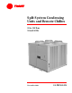
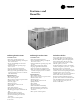
Split System Condensing Units and Remote Chillers 20 to 120Tons 50 and 60 Hz November 2001 SS-PRC005-EN
Introduction Trane 20 through 120-ton air-cooled condensing units are the leaders in the split system marketplace. Designed for efficiency, reliability and flexibility, the Trane units have the most advanced design in the industry. ©American Standard Inc. 2001 Twenty through 120-ton units feature theTrane 3-D™ Scroll compressor, solidstate controls andTrane’s exclusive Packed Stock Plus availability for quick shipment.
Contents Introduction Features and Benefits 2 Application Considerations 6 Selection Procedure 7 4 Model Number Description General Data 8 10 Performance Data 12 Performance Adjustment Factors SS-PRC005-EN Controls 11 25 Electric Power 27 Dimension and Weights 29 Mechanical Specifications 46 3
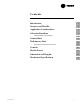
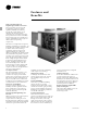
Features and Benefits Trane 3-D Scroll Compressor Simple Design with 70% Fewer Parts Fewer parts than an equal capacity reciprocating compressor means significant reliability and efficiency benefits. The single orbiting scroll eliminates the need for pistons, connecting rods, wrist pins and valves. Fewer parts lead to increased reliability. Fewer moving parts, less rotating mass and less internal friction means greater efficiency than reciprocating compressors.
Features and Benefits 20 Through 60-Ton Units 80 Through 120-Ton Units Packed Stock Plus Standard Features •Trane 3-D™ Scroll compressors • Factory-installed Discharge and Liquid Line Service Valves • Passive manifolding for 3-D Scroll compressors • Standard ambient operating range 40°F to 115°F • 14-gauge galvanized steel frame • Louvered panels for coil protection • Slate gray air-dry paint finish (exceeds 672 hour salt spray test in accordance with ASTM B117) Standard Features •Trane 3-D Scroll comp
Application Considerations Certain application constraints should be considered when sizing, selecting and installing Trane air-cooled condensing units. Unit reliability is dependent upon these considerations. Where your application varies from the guidelines presented, it should be reviewed with the localTrane sales engineer. Unit Sizing Unit capacities are listed in the performance data section on pages 11 to 24. Intentionally oversizing a unit to assure adequate capacity is not recommended.
Selection Procedure RAUC/AIR HANDLER Standard Selection Procedure Selection Procedure Net capacity curves for the RAUC condensing units are given on pages 14 through 23.These graphs can be used to cross plot an evaporator (EVP) performance curve. The resultant point of intersection will be the system design balance point. The design operating suction temperature and capacity can then be read directly from the graph.
Model Number Description 20 - 60Ton Air-Cooled Condensing Units 20 TO 60-TON AIR-COOLED CONDENSING UNITS1 R 1 A 2 U 3 C 4 C20 5,6,7 E 8 DIGIT 1 — UNIT TYPE R = Condensing Unit DIGIT 2 — CONDENSER A = Air Cooled DIGIT 3 — AIRFLOW U = Upflow DIGIT 4 — DEVELOPMENT SEQUENCE C = Third DIGITS 5,6,7 — NOMINAL CAPACITY C20 = 20Tons C25 = 25Tons C30 = 30Tons C40 = 40Tons C50 = 50Tons C60 = 60Tons B 9 A 10 1 11 0 12 A 13 0 14 0 15 DIGIT 8 — VOLTAGE AND START CHARACTERISTICS E = 200/60/3 XL D = 4
Model Number Description 80 - 120Ton Air-Cooled Condensing Units 80 TO 120-TON AIR-COOLED CONDENSING UNIT1 R 1 A 2 U 3 C 4 C80 5,6,7 4 8 DIGIT 1 — UNIT TYPE R = Remote Condensing Unit DIGIT 2 — CONDENSER A = Air-Cooled DIGIT 3 — AIRFLOW U = Upflow DIGIT 4 — DEVELOPMENT SEQUENCE C = Third B 9 A 10 0 11 0 12 2 13 B 14 0 15 DIGIT 8 — VOLTAGE AND START CHARACTERISTICS E = 200/60/3 XL D = 415/50/3 XL F = 230/60/3 XL 4 = 460/60/3 XL 5 = 575/60/3 XL 9 = 380/50/3 XL 0 16 0 17 0 18 0 19 DIG
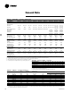
General Data Table GD-1 — General Data — 20-120 Ton Condensing Units Nominal Tonnage Model Number Compressor Data Type Manifolded Sets Circuit #1 Circuit # 2 Unit Capacity Steps (%) No Control & VAV Option EVP Option Condenser Fan Data Quantity/Fan Dia./Type Fan Drive Type No. of Motors/Hp Each NominalTotal Cfm Condenser Coil Data Number of Coils/Size (Inches) Face Area (Sq. Ft.) Rows/Fins Per Ft. Condenser Storage Capacity (Lbs.) (2) Refrigerant Data (3) No.
Performance Adjustment Factors Table PAF-1 — Altitude Correction Multiplier for Capacity Altitude (Ft.) Condensing Unit Only Condensing Unit / Air Handling Unit Combination Condensing Unit With Evap. 2,000 0.982 0.983 0.986 4,000 0.960 0.963 0.968 6,000 0.933 0.939 0.947 8,000 0.902 0.911 0.921 10,000 0.866 0.881 0.891 Table PAF-2 — Glycol Adjustment Factor for 20-60 Ton Split Condensing Units with the Remote Chiller (EVP) Option Leaving Solution Temp.
Performance Data 20 - 60Tons Table PD-1 — Gross System Capacity Data — 20-60 Ton Condensing Unit with Evaporator Chiller Condensing Unit-Nominal Tons Model RAUC C20 With 20 Ton Chiller 20 RAUC C20 With 25 Ton Chiller RAUC C25 With 25 Ton Chiller 25 RAUC C25 With 30 Ton Chiller 30 RAUC C30 With 30 Ton Chiller RAUC C40 With 40 Ton Chiller 40 RAUC C40 With 50 Ton Chiller RAUC C50 With 50 Ton Chiller 50 RAUC C50 With 60 Ton Chiller RAUC C60 With 60 Ton Chiller 60 RAUC C60 With 80 Ton Chiller 12 Leaving
Performance Data 80 - 120Tons Table PD-2 — Gross System Capacity Data — 80-120 Ton Condensing Unit with Evaporator Chiller Condensing Unit-Nominal Tons Model RAUC C80 With 60 Ton Chiller RAUC C80 With 80 Ton Chiller 80 RAUC C80 With 100 Ton Chiller RAUC D10 With 80 Ton Chiller RAUC D10 With 100 Ton Chiller 100 RAUC D10 With 120 Ton Chiller RAUC D12 With 100 Ton Chiller 120 RAUC D12 With 120 Ton Chiller Leaving Chilled Water Temp.
Performance Data — 60 Hz 20 & 25Ton Condensing Units Chart PD-1 — 20 Ton Condensing Unit Performance — RAUC-C20 (60 HZ) Chart PD-2 — 25 Ton Condensing Unit Performance — RAUC-C25 (60 HZ) 14 SS-PRC005-EN
Performance Data — 50 Hz RAUC-C20 & C25 Condensing Units Chart PD-3 — 20 Ton Condensing Unit Performance — RAUC-C20 (50 HZ) Chart PD-4 — 25 Ton Condensing Unit Performance — RAUC-C25 (50 HZ) SS-PRC005-EN 15
Performance Data — 60 Hz 30 & 40Ton Condensing Units Chart PD-5 — 30 Ton Condensing Unit Performance — RAUC-C30 (60 HZ) Chart PD-6— 40 Ton Condensing Unit Performance — RAUC-C40 (60 HZ) 16 SS-PRC005-EN
Performance Data — 50 Hz RAUC-C30 & C40 Condensing Units Chart PD-7 — 30 Ton Condensing Unit Performance — RAUC-C30 (50 HZ) Chart PD-8 — 40 Ton Condensing Unit Performance — RAUC-C40 (50 HZ) SS-PRC005-EN 17
Performance Data — 60 Hz 50 & 60Ton Condensing Units Chart PD-9 — 50 Ton Condensing Unit Performance — RAUC-C50 (60 HZ) Chart PD-10— 60 Ton Condensing Unit Performance — RAUC-C60 (60 HZ) 18 SS-PRC005-EN
Performance Data — 50 Hz RAUC-C50 & C60 Condensing Units Chart PD-11 — 50 Ton Condensing Unit Performance — RAUC-C50 (50 HZ) Chart PD-12 — 60 Ton Condensing Unit Performance — RAUC-C60 (50 HZ) SS-PRC005-EN 19
Performance Data — 60 Hz 80 & 100Ton Condensing Units Chart PD-13 — 80 Ton Condensing Unit Performance — RAUC-C80 (60 HZ) Chart PD-14 — 100 Ton Condensing Unit Performance — RAUC-D10 (60 HZ) 20 SS-PRC005-EN
Performance Data — 50 Hz RAUC-C80 & D10 Condensing Units Chart PD-15 — 80 Ton Condensing Unit Performance — RAUC-C80 (50 HZ) Chart PD-16 — 100 Ton Condensing Unit Performance — RAUC-D10 (50 HZ) SS-PRC005-EN 21
Performance Data — 60 Hz 120Ton Condensing Units Chart PD-17 — 120 Ton Condensing Unit Performance — RAUC-D12 (60 HZ) Chart PD-18 – EVP Performance Curve – 20 through 40 Tons 20-60 Ton Evaporator Chiller Option 22 SS-PRC005-EN
Performance Data — 50 Hz RAUC-D12 Condensing Units Chart PD-19 — 120 Ton Condensing Unit Performance — RAUC-D12 (50 HZ) SS-PRC005-EN 23
Performance Data — 60 HZ 20-60 Ton Evaporator Chiller Option Chart PD-20 — EVP Performance Curve — 50 and 60 Tons Chart PD-21 — EVP Performance Curve — 80 through 120 Tons 80-120 Ton Evaporator Chiller Option 24 SS-PRC005-EN
Standard Options 20 through 60-Ton Condensing Units System Control Options Select one of the four following control options to meet your application requirements. • No System Control provides the compressors wired to a terminal strip inside the control panel. The temperature controller must be field provided and installed. The 20, 25 and 30-ton have two capacity steps. The 40, 50 and 60-ton sizes have four steps available.
Standard Options 80 through 120-Ton Condensing Units System Control Options Select one of the three following control options to meet your application requirements. • Supply Air VAV includes a multi-step, demand oriented, microprocessor-based Honeywell W7100 discharge air controller. W7100 control is designed for shut-off VAV systems. Average discharge air temperature is maintained by modulating an economizer and if needed, simultaneously sequencing stages of mechanical cooling.
Electrical Data Table ED-1 — Condensing Units — 60 Hz Nominal Tons 20 25 30 40 50 60 80 100 120 Model Number RAUC-C20E RAUC-C20F RAUC-C204 RAUC-C205 RAUC-C25E RAUC-C25F RAUC-C254 RAUC-C255 RAUC-C30E RAUC-C30F RAUC-C304 RAUC-C305 RAUC-C40E RAUC-C40F RAUC-C404 RAUC-C405 RAUC-C50E RAUC-C50F RAUC-C504 RAUC-C505 RAUC-C60E RAUC-C60F RAUC-C604 RAUC-C605 RAUC-C80E RAUC-C80F RAUC-C804 RAUC-C805 RAUC-D10E RAUC-D10F RAUC-D104 RAUC-D105 RAUC-D12E RAUC-D12F RAUC-D124 RAUC-D125 Voltage/Start Characteristics 2
Electrical Data Table ED-3 — Compressor Motor and Condenser Fan Data — 60 Hz Nominal Tons Model 20 RAUC-C20 25 RAUC-C25 30 RAUC-C30 40 RAUC-C40 50 RAUC-C50 60 RAUC-C60 Nominal Tons Model 80 RAUC-C80 100 RAUC-D10 120 RAUC-D12 Voltage 200 XL 230 XL 460 XL 575 XL 200 XL 230 XL 460 XL 575 XL 200 XL 230 XL 460 XL 575 XL 200 XL 230 XL 460 XL 575 XL 200 XL 230 XL 460 XL 575 XL 200 XL 230 XL 460 XL 575 XL Voltage 200 XL 230 XL 460 XL 575 XL 200 XL 230 XL 460 XL 575 XL 200 XL 230 XL 460 XL 575
Dimensional Data 20Ton Condensing Unit Figure DD-1 — Air-Cooled Condensing Unit — RAUC 20 Ton SS-PRC005-EN 29
Dimensional Data 25Ton Condensing Unit Figure DD-2 — Air-Cooled Condensing Unit — RAUC 25 Ton 30 SS-PRC005-EN
Dimensional Data 30Ton Condensing Unit Figure DD-3 — Air-Cooled Condensing Unit — RAUC 30 Ton SS-PRC005-EN 31
Dimensional Data 40Ton Condensing Unit Figure DD-4 — Air-Cooled Condensing Unit — RAUC 40 Ton 32 SS-PRC005-EN
Dimensional Data 50Ton Condensing Unit Figure DD-5 — Air-Cooled Condensing Unit — RAUC 50 Ton SS-PRC005-EN 33
Dimensional Data 60Ton Condensing Unit Figure DD-6 — Air-Cooled Condensing Unit — RAUC 60 Ton 34 SS-PRC005-EN
Dimensional Data 80Ton Condensing Unit Figure DD-7 — Air-Cooled Condensing Unit — RAUC 80 Ton NOTES: 1. Hot gas bypass, suction and liquid line connection locations shown in the front view do not represent holes in the unit panel. Access to these connections are provided by the customers. 2. Dimensional tolerance is ±1/8”.
Dimensional Data 100Ton Condensing Unit Figure DD-8 — Air-Cooled Condensing Unit — RAUC 100 Ton NOTES: 1. Hot gas bypass, suction and liquid line connection locations shown in the front view do not represent holes in the unit panel. Access to these connections are provided by the customers. 2. Dimensional tolerance is ±1/8”.
Dimensional Data 120Ton Condensing Unit Figure DD-9 — Air-Cooled Condensing Unit — RAUC 120 Ton NOTES: 1. Hot gas bypass, suction and liquid line connection locations shown in the front view do not represent holes in the unit panel. Access to these connections are provided by the customers. 2. Dimensional tolerance is ±1/8”.
Dimensional Data 20 and 25Ton Evaporator Chiller Figure DD-10 — 20 and 25-Ton Evapo rator Chiller Evaporator Flange Connection. Flange adapter and O-ring supplied byTrane. NOTES: 1. DIMENSIONAL TOLERANCE IS ± 1/8”. 2.
Dimensional Data 30Ton Evaporator Chiller Figure DD-11 — 30-Ton Evaporator Chiller NOTES: 1. DIMENSIONAL TOLERANCE IS ± 1/8”. 2. ALLOW 6’2” TUBE REMOVAL CLEARANCE EITHER END OF EVAPORATOR SS-PRC005-EN Evaporator Flange Connection. Flange adapter and O-ring supplied byTrane.
Dimensional Data 40Ton Evaporator Chiller Figure DD-12 — 40-Ton Evaporator Chiller NOTES: 1. DIMENSIONAL TOLERANCE IS ± 1/8”. 2.
Dimensional Data 50Ton and 60Ton Evaporator Chiller Figure DD-13 — 50 and 60-Ton Evaporator Chiller NOTES: 1. DIMENSIONAL TOLERANCE IS ± 1/8”. 2.
Dimensional Data 80Ton Evaporator Chiller Figure DD-14 — 80-Ton Evaporator Chiller Evaporator Flange Connection.
Dimensional Data 100Ton Evaporator Chiller Figure DD-15 — 100-Ton Evaporator Chiller Evaporator Flange Connection.
Dimensional Data 120Ton Evaporator Chiller Figure DD-16 — 120-Ton Evaporator Chiller Evaporator Flange Connection.
Weights Table W-1 — 20-60 Ton Air-Cooled Condensing Units Nominal Tons 20 25 30 40 50 60 Model RAUC-C20 RAUC-C25 RAUC-C30 RAUC-C40 RAUC-C50 RAUC-C60 Operating Weight (Lbs.) AL CU 1522 1720 1640 1842 1824 2115 2769 3102 3148 3540 3480 4050 Loc. 1 AL CU 509 559 555 602 580 640 480 523 586 643 640 722 Loc. 2 AL CU 398 439 421 467 635 708 457 501 562 620 618 703 Weight On Isolator At Mounting Locations (Lbs.) Loc. 3 Loc. 4 Loc.
Mechanical Specifications 20 through 60-ton Condensing Units General All air-cooledcondensing units have scroll compressors and are factory assembled and wired. Each unit is shipped from the factory with a nitrogen holding charge. Units are constructed of 14-gauge welded galvanized steel frame with 14 and 16-gauge galvanized steel panels and access doors. Unit surface is phosphatized and finished with an air-dry paint.
Trane A business of American Standard Companies www.trane.com For more information contact your local district office, or e-mail us at comfort@trane.com Literature Order Number SS-PRC005-EN File Number PL-UN-SS-PRC005-EN-11-2001 Supersedes SS-PRC005-EN-07-2001 Stocking Location Webb/Mason Trane has a policy of continuous product and product data improvement and reserves the right to change design and specifications without notice.