Ffirm TrangoLINK-45™ Point-to-Point Wireless Ethernet Bridge USER MANUAL June, 2007 Revision 1p3
Preface Table of Contents Preface...................................................................................................................................................................iv FCC Information .......................................................................................................iv Industry Canada Information..................................................................................... v Warranty Information .....................................................
Table of Figures Trango Chapter 6 Firmware Upgrade Procedure ..............................................................................................................39 Firmware File Names .............................................................................................. 39 Firmware Upgrade Password ................................................................................... 39 Upgrade Procedure ......................................................................................
Preface Preface This manual covers the basic configuration and installation of the TrangoLINK-45 Wireless Point to Point Broadband System, and applies to the following radio part numbers: P5055M-19-xx P5055M-23-xx P5055M-EXT-xx Radio unit with internal 19 dBi patch antenna array Radio unit with internal 23 dBi patch antenna array Radio unit with external RP-SMA antenna connectors Where “xx” denotes the regulatory configuration of the unit as follows: US: For use in the USA IC: For use in Canada EU: For u
Preface Industry Canada InformationIndustry Canada InformationIndustry Canada Information WARNING: Intentional or unintentional changes or modifications must not be made unless under the express consent of the party responsible for compliance. Any such modifications could void the user’s authority to operate the equipment and will void the manufacturer’s warranty. To comply with RF exposure requirements, the following antenna installation and device operating configurations must be satisfied.
Preface Europe InformationEurope InformationEurope Information Europe Information We, Trango Systems, Inc.
Preface Contact Information Corporate Headquarters Web Sites Sales Inquiries Technical Support Firmware Update Notices Mailing List Trango Broadband Wireless — TrangoLINK-45 Europe InformationEurope InformationEurope Information Trango Broadband Wireless, a division of Trango Systems, Inc. 15070 Avenue of Science Suite 200 San Diego, CA 92128 USA www.trangobroadband.com www.trangosys.com email: sales@trangobroadband.com Telephone: 1-858-653-3900 email: techsupport@trangobroadband.
Overview DFS Chapter 1 Overview The TrangoLINK-45 is a point-to-point (PtP) wireless Ethernet transmission system which provides network connectivity at speeds up to 45 Mbps depending on the transmission distance and noise floor. The TrangoLINK-45 utilizes OFDM technology and is designed for use in long range backhaul and wide area data networking applications. Users are required to simply specify one P5055M unit type as master unit (MU) and one unit as remote unit (RU) to establish a link.
Overview ARQ ARQ Another key advantage of the TrangoLINK-45 platform is its Automatic Repeat Request (ARQ) transmission correction scheme. The ARQ algorithm detects packet loss due to fading and interference conditions and requests the remote radio to re-transmit specific packets. Dual Polarity Antenna TrangoLINK-45 radios feature built-in dual polarity antenna functionality. Users may select either horizontal or vertical antenna polarity through the unit’s software.
Overview Range vs. Throughput Range vs. Throughput The following table shows approximate maximum ranges (at recommended fade margins) achievable with the TrangoLINK-45 system using various antenna configurations. Longer ranges are achievable, but will result in lower fade margins. To estimate theoretical throughput and fade margin for any distance, download the link budget / fade margin calculator tool from www.trangobroadband.com .
Overview System Contents System Contents The TrangoLINK-45 system is available in two versions: TrangoLINK-45-19-xx TrangoLINK-45-23-xx TrangoLINK-45-EXT-xx - Radios with integrated 19 dBi antennas (part numbers P5055M-19-xx) Radios with integrated 23 dBi antennas (part numbers P5055M-23-xx) Connectorized radios (part numbers P5055M-EXT-xx) Each TrangoLINK-45 kit consists of two radios, two power-over-Ethernet (PoE) injectors, two AC adapters, port covers, and mounting hardware.
Overview Location of Serial Number & MAC Address Location of Serial Number & MAC Address The serial number and MAC address label can be found on the back of each radio. The serial number and MAC address is also provided within the system information (sysinfo) screen. Trango Broadband Wireless P5055M- 23-US Rev.
Getting Started Connections and Power Chapter 2 Getting Started It is always a good idea to first provision and test the radios on the bench before deploying them in the field. This is a particularly useful exercise for the novice user. Connections and Power • Connect a Cat-5 (straight through) Ethernet cable (we recommend shielded twisted pair) between the ODU (out door unit) port of the J-box and the RJ-45 connector on the radio. Note that this cable will carry power-overEthernet (PoE).
Getting Started Configuration Tools Configuration Tools P5055M radios can be configured using either the Command Line Interface (CLI), or the Web Browser (HTTP) interface. The CLI method provides slightly more functionality. This text covers configuration through the CLI. For HTTP configuration please see Appendix A. Telnet Open a command prompt (DOS) session on your PC. Open a Telnet session by typing: telnet Example: C:>telnet 192.168.100.
Getting Started Troubleshooting Ethernet Connections Troubleshooting Ethernet Connections If you cannot telnet into the radio or open an HTTP browser session, check your cable connections to ensure proper use of cross-over vs. straight-through cable, and ensure your PC’s subnet is routable to the radio’s IP address. System Information (sysinfo) Page To display system configuration and status information type the command sysinfo.
Getting Started System Information (sysinfo) Page Sysinfo Example: #> sysinfo ********************************* 0 ********************************* [Model] P5055M [Area Code] 0 [Unit Type] RU [Hardware Version] 5055 [Firmware Version] 2p0r1D07061104 [System Up Time] 7 day(s) 03:58:16 ********************************* 1 ********************************* [MAC] 00 01 DE 61 59 F7 [S/N] 6380023 [IP] 10.8.2.149 [Subnet Mask] 255.255.255.224 [Gateway] 10.8.2.
Getting Started System Information (sysinfo) Page ********************************* 5 ********************************* [Tx MIR] 50000 Kbps [ARQ] on [Encrypt] off [Key] 0011 2233 4455 6677 8899 AABB CCDD EEFF [Auto Rate Shift] on [Auto Scan MU] off [RSSI LED] on [Remarks] Remarks ********************************* 6 ********************************* [Eth Config] ANEG [Eth Status] 100 FDX [Eth In] 35,262,413 bytes [Eth Out] 9,201,047 bytes [RF In] 0 bytes 0 Kbps [RF Out] 0 bytes 0 Kbps 3 Kbps 51 Kbps [ARQ
Getting Started [S/N] [IP] [Subnet Mask] [Gateway] System Information (sysinfo) Page Serial Number of Radio User defined IP Address of radio User entered IP Subnet Mask User entered IP address of the default router or gateway on the local Ethernet segment Section 2 [PoE Voltage] [Radio Temp] [Opmode] [Default Opmode] [Active Channel] [Freq] [Speed] [Tx Power] [Power Range] [Peer ID] [Status] [RSSI] [Peer IP Config] [DFS Status] The voltage the ODU received from the Jbox.
Getting Started [Remarks] System Information (sysinfo) Page User entered remarks up to 256 characters. Field accepts alpha numeric’s only. Special characters (!@#$%^&*()\?/) require quotations.
Configuration Key Concepts Chapter 3 Configuration Key Concepts Prior to configuring the radios it is important to understand several key concepts: Master Unit (MU) The MU is typically considered the primary radio within the link. For management purposes it is recommended to install the MU closest to the head-end of the network. Remote Unit (RU) The RU is typically installed at the remote end of the link.
Configuration 2. Remote Unit Configuration Set the Peer ID with the MAC address of the RU. Only use the last 8 digits of the MAC address. #> peerid de1B7850 Success. #> 3. Set channel and polarization. (in this example set the channel to 2 and polarization to H). #> freq 2 h Ch# 23 h (5280 MHz) Success. 4. Set default Opmode to ON. #> defaultopmode on Success. 5.
Configuration Establishing a Wireless Link Establishing a Wireless Link If the MU and RU are properly configured and in opmode “ON”, the two radios will automatically begin the authentication process and become connected. To determine if the two radios are connected, type the sysinfo 2 command. Example: #> sysinfo 2 ********************************* 2 ********************************* [Radio Temp] 34 C [PoE Voltage] 14.
Configuration RF Link Loopback Test (linktest command) Yellow LED 1 : Begins blinking when RSSI is greater or equal to –90 dBm. On continuously at –85 dBm. This is the Leftmost LED Yellow LED 2 : Begins blinking when RSSI is greater or equal to –80 dBm. On continuously at –75 dBm. Yellow LED 3 : Begins blinking when RSSI is greater or equal to –70 dBm. On continuously at –65 dBm. Yellow LED 4 : Begins blinking when RSSI is greater or equal to –60 dBm. On continuously at –55 dBm. This is the rightmost LED.
Configuration RF Link Loopback Test (linktest command) Success. #> In this example the linktest was run at 24 Mbps at each end of the link. The results indicated 10 cycles of 1000 packets were transmitted and received from each end of the link without error. Actual achievable throughput is measured at 22 Mbps.
Configuration Link Speed & Power Settings Link Speed & Power Settings Users may change the radio’s over-the-air data rate and conducted output power using the speed and power commands. Keep in mind that the lower data rates offer higher receiver sensitivity and higher allowable conducted RF power in the ISM band. The following table shows the relation between speed settings, modulation scheme, receiver sensitivity, and allowable maximum power settings for each frequency band.
Configuration MU Autoscan Feature Description In this example the user sets the power to 19dBm and the speed to 24 Mbps: #> power 19 Execution in progress... . 19 dBm (-4..19) Success. #> speed 24 24 Mbps Success. #> MU Autoscan Feature Description This feature allows the RU to actively search all channels and polarizations for its peer MU in the event of a disassociation. This feature is useful if the user frequently changes the channel/polarization of the MU .
Configuration Automatic Rate Shifting Feature Description Automatic Rate Shifting Feature Description With autorateshift feature enabled, the radios will automatically renegotiate the modulation method and speed speed to maximize wireless link integrity. The link speed will vary depending on two factors: 1) the number of ARQ errors received, 2)successful processing of special link assessment packets sent in both the current and next higher speed.
Configuration Encryption Feature Description Encryption Feature Description The TrangoLINK-45 system offers 128 bit proprietary encryption which may be turned on or off by the user. The HEX encryption key must be set in both the MU and RU. Users can expect faster payload speeds with encryption turned off as compared to with encryption turned on. Example: #> encrypt on Success. #> encrypt key 1111 2222 3333 4444 5555 6666 7777 8888 argc = 10 Success.
Configuration Command Reference Listing Command Reference Listing The complete command set reference is provided below. You can also view a complete listing of all CLI commands by typing help. Command Syntax antenna [h|v] arq [on|off] autorateshift [on|off] Description Set or display antenna setting. H=Horizontal polarity, V=vertical polarity. Enable or disable Auto Retransmit Request (ARQ). With ARQ enabled, the TrangoLINK-45 system will retransmit packets which are detected as missing or corrupted.
Configuration defaultopmode [on|off] encrypt [on|off] encrypt key exit freq [ ] freq writechannel … freq writechannel default help [] ipconfig [ ] linktest [ [<# of pkt> [<# of cycle>]]] mir [] opmode [on|off] password peerid [] power [] reboot remarks reset rssi rssiled [on|off] speed [] survey [] survey all survey [ [..
Configuration sysinfo [[ [ [..]]]] syslog tftpd [on|off] utype [mu|ru] Trango Broadband Wireless — TrangoLINK-45 Command Reference Listing Display system information and status = 0..6 part 0: up time and version information part 1: MAC address and IP configuration part 2: RF link status part 3: channel table part 4: region code and power limitations part 5: switch settings and remarks part 6: statistics Display system log. Enable or disable tftpd (used for firmware upgrades).
Deployment & Installation Site Selection Chapter 4 Deployment & Installation Once you are familiar with the basic operation of the radios you are ready for deployment in the field. The deployment process consists of the following steps: • Site Selection • Site survey at MU and RU sites • MU installation • RU installation and antenna alignment • Link test Site Selection Proper site selection for your MU will help ensure a successful deployment.
Deployment & Installation Ch 5 v Ch 6 h 5520 Ch 6 v Ch 7 h 5540 Ch 7 v Ch 8 h 5560 Ch 8 v Ch 9 h 5580 Ch 9 v Ch 10 h 5600 Ch 10 v Ch 11 h 5620 Ch 11 v Ch 12 h 5640 Ch 12 v Ch 13 h 5660 Ch 13 v Ch 14 h 5680 Ch 14 v Ch 15 h 5700 Ch 15 v Ch 16 h 5735 Ch 16 v Ch 17 h 5755 Ch 17 v Ch 18 h 5775 Ch 18 v Ch 19 h 5795 Ch 19 v Ch 20 h 5815 Ch 20 v Ch 21 h 5835 Ch 21 v Ch 22 h 5840 Ch 22 v Ch 23 h 5840 Ch 23 v Ch 24 h 5840 Ch 24 v Success.
Deployment & Installation RSSI Command and Antenna Alignment RSSI Command and Antenna Alignment Once the site survey is completed, you are ready to install your radios. Typically it is best to install the MU first. To properly align the radios, use the built-in RSSI tool to achieve maximum signal strength. 1. Ensure MU and RU are in Opmode “ON.” 2. Connect to the RU. 3. Login and type the command rssi.
Deployment & Installation Mounting Hardware Port Plug and Port Plate (Hardware) Prior to deployment, insert the silicone port plug around the Cat-5 Cable and insert into the radio’s port opening. Next, screw the port plate over the silicone plug as shown in the photographs below. Mounting Hardware Radios are supplied with mounting hardware for pole installations. See diagram below for proper use of the mounting hardware. 8.50 MAX 10.00° UPTILT 25.
Deployment & Installation Connecting External Antenna on EXT Model Mounting Hardware Assembly for P5055M-EXT-xx Connecting External Antenna on EXT Model The P5055-EXT-xx is equipped with two reverse-polarity SMA connectors on the top for attachment to an external antenna. Each SMA connector is labeled with either “V” for Vertical or “H” for Horizontal polarization. Connect each cable to the appropriate “H” and “V” ports on both the antenna and the radio.
Deployment & Installation Grounding Grounding Proper mounting of the radio includes consideration for grounding. Please note that if the radio is attached to a metal pole that is earth-grounded, no other grounding is necessary. If the radio is not earth-grounded via the mounting bracket, you must attach a grounding wire to the grounding stud on the radio as in the adjacent diagram. Grounding Wire Cat-5 Cabling Considerations Shielded twisted pair Cat-5 cable is recommended for all installations.
SNMP SNMP Chapter 5 SNMP SNMP The TrangoLINK-45 supports SNMP (Simple Network Management Protocol). Network management consists of the following 3 categories: configuration, Link and Association monitoring and Alarms. Besides this proprietary Management Information Base (MIB) the TrangoLINK-45 also supports a large part of the MIB-II OIDs. Review the Trango MIB (TRANGO-P5M-MIB.mib) available on our website for the complete listing of all MIB objects available.
Firmware Upgrade Procedure Firmware File Names Chapter 6 Firmware Upgrade Procedure Trango Broadband Wireless will from time to time release firmware upgrades for the TrangoLINK-45 series radios. The latest released firmware can be downloaded from http://www.trangobroadband.com/support/downloads.htm. Firmware releases consists of two files: Main image firmware and Web (HTTP interface) firmware. Firmware File Names Firmware files are released in the format shown below.
Firmware Upgrade Procedure Example 1 Upgrade main image firmware to 1.0a6 Success. #> FROM COMPUTER COMMAND PROMPT SESSION C:\TrangoLINK-45>dir Volume in drive C is Local Disk Volume Serial Number is 7802-AAF7 Directory of C:\TrangoLINK-45 06/16/2007 06/16/2007 06/11/2007 05/17/2007 2 File(s) 08:29a
. 08:29a ..Appendix A Appendix A Using the HTTP Interface Open a browser session and type in the IP address of one of the radios. Default IP address is 192.168.100.100. Leave the User name field blank and enter read write or read only Password. Press OK. Default password is trango. After logging on, the system information screen will be displayed.
Appendix A Navigation links are shown on the left side of the browser screen. Navigable links include: System Information Configuration Site Survey Link Control Help The lower left portion of the screen shows the unit’s current opmode, connection, channel, and antenna status. The main body of the System Information displays most of the key parameters. To alter these parameters use the Configuration page.
Appendix A Model: Model number. Unit Type: P5055M unit type either MU (master) or RU (remote). Hardware Version: Hardware version is factory-set and can not be changed by user. Firmware Version: Current firmware version loaded in the radio. System Up Time: Time since radio was last rebooted or powered. MAC: MAC address of the radio. IP, Subnet Mask, Gateway: IP, subnet mask, and gateway of radio Opmode: Current operation of the radio.\"On\" indicates transmitting.
Appendix A RF Out: Counter for Ethernet packets which exited over-the-air out the radio. Configuration Page IP Address: The IP address of this radio; used to manage the radio's application layer. Subnet Mask: The subnet mask of the radio. Gateway: The default gateway of the radio. Default Opmode: Operation mode of the radio after power cycle. When Opmode is \"On\" the radio will attempt to make a wireless connection.
Appendix A Reboot: Reboot the unit. Close All Telnet Sessions: Close all the active telnet sessions. Configuration Screen All user configurable parameters can be entered from the Configuration Screen and this is the only screen used to provision a wireless link between the two radios.
Appendix A IP Configuration: Each radio should be set up with a unique IP address to enable remote management. Click on “Change IP Config” to save the setting. Default Opmode: Should be “On”. Radio will enter default opmode approximately 30 seconds after complete reboot cycle. Opmode must be “On” for radios to transmit and wirelessly connect. Peer ID: Enter the last 8 digits of the peer units MAC address. P5055M radios will only wirelessly connect to the peer ID with the specified MAC address.
Appendix A Site Survey Page The site survey function measures overall noise floor as well as in-band noise containing data packets. Noise is reported in terms of average and peak dBm for the period tested. The user specifies duration of the test in minutes as well as the antenna port. To run a site survey, the radio must be in Opmode OFF. In this example the site survey function was performed for 1 minute on the vertical polarity.
Appendix A Link Control The Link Control page features the RF Link Loopback / Speed Test. In this test, the user specifies the transmission rate (in Mbps) in both the local radio and the peer radio as well as the duration time (in minutes) for the test. During the test, the local radio will transmit packets across the wireless link. The peer radio will retransmit equivalent packets back to the local radio. The test will measure and report error rate and actual throughput as measured in Mbps.
Appendix B Specifications Appendix B Specifications RF Parameters RF Conducted Power and Receiver sensitivity for 1x10⁻³ Frame error rate with ARQ active: Speed Setting (over-the-air rate) (Mbps) Modulation Scheme - US / IC MODELS* Receiver Max Power Sensitivity 5.18 to 5.24 GHz (dB) (dBm) Max Power 5.265- 5.325, 5.5 to 5.7 GHz (DFS-UNII) (dBm) Max Power 5.735 to 5.
Appendix B RF Data Rate: Error Correction: Modulation: Specifications 6, 12, 18, 24, 36, 48, 54 MBPS User selectable FEC & ARQ 6 MBPS DBPSK OFDM for header, 6-54 MBPS OFDM for payload Channels of Operation Storable Channels: 24 memory locations Center frequency ranges: (-US models) Band 1: Band 2: Band 3: Band 4: NA 5.265 to 5.325 GHz (DFS) 5.500 to 5.700 GHz (DFS) 5.735 to 5.840 GHz (-IC models) Band 1: Band 2: Band 3: Band 4: NA 5.265 to 5.325 GHz (DFS) 5.500 to 5.700 GHz (DFS) excluding 5.600-5.
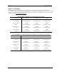
Appendix B Specifications Channel 13: 5.660 GHz Channel 14: 5.680 GHz Channel 15: 5.700 GHz Channel 16: 5.735 GHz Channel 17: 5.755 GHz Channel 18: 5.775 GHz Channel 19: 5.795 GHz Channel 20: 5.815 GHz Channel 21: 5.835 GHz Channel 22: 5.840 GHz Channel 23: 5.840 GHz Channel 24: 5.840 GHz (-IC Models) Channel 1: 5.265 GHz Channel 2: 5.285 GHz Channel 3: 5.305 GHz Channel 4: 5.325 GHz Channel 5: 5.500 GHz Channel 6: 5.520 GHz Channel 7: 5.540 GHz Channel 8: 5.560 GHz Channel 9: 5.
Appendix B Specifications Channel 18: 5.680 GHz Channel 19: 5.700 GHz Channel 20: Disabled Channel 21: Disabled Channel 22: Disabled Channel 23: Disabled Channel 24: Disabled (-OE Models) Channel 1: 5.180 GHz Channel 2: 5.200 GHz Channel 3: 5.220 GHz Channel 4: 5.240 GHz Channel 5: 5.260 GHz Channel 6: 5.280 GHz Channel 7: 5.300 GHz Channel 8: 5.320 GHz Channel 9: 5.500 GHz Channel 10: 5.520 GHz Channel 11: 5.540 GHz Channel 12: 5.560 GHz Channel 13: 5.580 GHz Channel 14: 5.600 GHz Channel 15: 5.
Appendix B Specifications EN 50385 Canada Standards RSS-210 RSS-102 ICES-003 Mechanical Material: Powdercoated Aluminum case/back with UV Stabilized ABS radome (P5055-19,-23) Size: 8.5" x 7.75" for P5055M-19-xx 15” x 15” for P5055M-23-xx 5” X 5” for P5055M-EXT –xx Weight: P5055M-19-xx: 4 lb P5055M-23-xx: 7 lb P5055M-EXT-xx: 4 lb Mounting: Custom pole/flat surface mounting with elevation adjustment.
Appendix B Specifications Antennas Integrated 19 dBi Antenna (for P5055M-19-xx) Frequency range: 4950-5850 MHz Gain: 19 dBi +/- 1 dB Front/Back Ratio >30 dB E-Plane Beamwidth: > 18 degrees typical H-Plane Beamwidth: > 18 degrees typical Polarization: Vertical and Horizontal Port/Port Isolation: 20 dB typ Cross Pol Rejection: 20 dB typ VSWR: <1.7:1 Package: Alumininum backplate with plastic radome. Dimensions: 8.5" x 7.75" x 1.25" (216mm x 197mm x 32mm) Weight: 2 lbs (.