
TV Converter Box User Manual
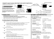

MDI switch setting
MDI-X switch setting
100 meters
100 meters
2 kilometers - multimode
20 kilometers - singlemode
Straight Through/Crossover Cable Requirements and Pin Specifications
The two active pairs in a CDDI
network are pins 1 & 2 and
pins 7 & 8. Use only dedicated
wire pairs (such as blue/white
& white/blue, orange/white &
white/orange) for the active
pins.
1
2
7
8
Twisted
Pair #1
Twisted
Pair #2
Straight Through Cable
1
2
7
8
Straight-through/crossover CDDI requirements are satisfied using
the MDI/MDI-X switch with straight-through cable.
CDDI cable connections between a
concentrator and the media converter require
the MDI/MDI-X switch to be set to MDI.
CDDI cable connections between the media
converter and a NIC require the switch to be
set to MDI-X
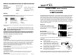
MDI
MDI-X
12V DC Input
FD-CD-01
CDDI
FDDI
FDDI to CDDI
MDI-X
position
MDI
position
Using small flatblade screwdriver
or similar tool and referring to
label at front of media converter,
set MDI/MDI-X switch position for
site installation.
CDDI Cable
1. Is the power LED on the media converter illuminated?
NO
• Is the power adapter the proper type of voltage and cycle frequency for your AC outlet?
NOTE: Refer to the “Power Supply Requirements” on the back page.
• Is the power adapter properly installed in the media converter and in the outlet?
• Contact Technical Support at (800) 260-1312/ (800) LAN-WANS.
YES
• Proceed to step 2.
2. Is the CDDI Link LED illuminated?
NO
• Check UTP cables for proper connection and pin assignment. (See above.)
• Contact Technical Support at (800) 260-1312/ (800) LAN-WANS.
YES
• Proceed to step 3.
3. Is the fiber Link LED illuminated?
NO
• Check fiber cables for proper connection.
• Verify that TX and RX cables on media converter are connected to RX and TX ports,
respectively, on the other FDDI device.
• Refer to Tech Tips available at: http://www.transition.com
• Contact Technical Support at (800) 260-1312/ (800) LAN-WANS.
YES
• Contact Technical Support at (800) 260-1312/ (800) LAN-WANS.
Troubleshooting the Media Converter
Installation Notes
The physical characteristics of the media cable must meet or exceed ANSI
X3T12 FDDI specifications.
ETHERNET CABLE SPECIFICATIONS
FDDI CABLE SPECIFICATIONS
SINGLEMODE
Fiber-optic Cable Recommended: 9 µm singlemode fiber
Fiber-optic Transmitter Power: min: -15.0 dBm max: -8.0 dBm
Fiber-optic Receiver Sensitivity: min: -32.5
dBm max: -8.0
dBm
Wavelength: 1300nM
Bit error rate: ≤10
-9
Maximum Cable Distance: 20 kilometers
MULTIMODE
Fiber-optic Cable Recommended: 62.5 / 125 µm multimode fiber
Optional: 100 / 140 µm multimode fiber
85 / 125 µm multimode fiber
50 / 125 µm multimode fiber
Fiber-optic Transmitter Power: min: -19.0
dBm max: -14.0 dBm
Fiber-optic Receiver Sensitivity: min: -32.5 dBm max: -14.0 dBm
Wavelength: 1300nM
Bit error rate: ≤10
-9
Maximum Cable Distance: 2 kilometers
CDDI CABLE SPECIFICATIONS
Category 5 wire or better is required. Either shielded twisted pair
(STP) or unshielded twisted pair (UTP) can be used. DO NOT USE
FLAT OR SILVER SATIN WIRE.
CATEGORY 5:
Gauge 24 to 22 AWG
Attenuation 20 dB/1000’ @ 10 MHz
Impedance 100 Ω ±10% @ 10 MHz
Maximum Cable Distance: 100 meters (330 feet)
• KEEP TWISTED PAIR RUNS AS SHORT AS POSSIBLE.
• Be certain that the CDDI MDI/MDI-X switch is set correctly for site installation.
• Connect the power supply cable to the media converter BEFORE connecting to the outlet.
• Install unit with PSU provided. (Output 12 VDC regulated, 350 mA).
• Install no more than two (2) media converters in series.
FD-CD-01, FD-CD-01(SM)