
Stand-Alone Devices Installation Operation

4
SSDTF10xx-10x
Installation -- Continued
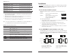
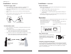
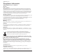
Set the loop-back switch
Hardware mode:
The loop-back switch is located on the front panel of the device and is used for
installation and network debugging procedures.
To set the switch, use a small flat-blade screwdriver or a
similar device (see the drawing to the right).
CL (Copper loop-back) Enable loop-back on the
local copper interface.
-- (Center Position) Normal operation.
FL (Fiber loop-back) Enable loop-back on the local fiber interface.
Software mode:
If both Devices are under software control, the network administrator can initiate
the loop-back test function on the copper interface (local or remote) or on the fiber
interface (local or remote). These four loop-back test scenarios are described in
detail on page 14.
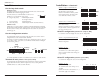
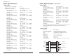
Set the configuration switches
The configuration switches are located on the side of the device and are used to
configure the device for various network conditions.
The switches are labeled 1 through 8 on the device housing top. There are two sets
(a “left, SW 2” and a “right, SW 1”) each with four switches labeled 1 through 4
(see the drawing below).
Use a small, flat-blade screwdriver or a similar device to set the recessed switches.
Transmit all ones (switches 1 & 2, left set, SW 2)
The Transmit All Ones function allows the insertion of an “all ones” pattern on the
copper and/or fiber interface when the signal detect is lost, creating an alarm
condition at the device connected to the interface.
CL
FL
SW 2 SW 1
R
ear
Cable End
Cover Top
Config
Switches
1234 1234 Switch Numbers
56781234
Key:
UP
DOWN
Not Use
d
.
5
Installation -- Continued
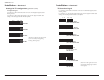
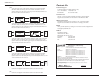
Switch 1, Copper -- transmit all ones
UP - Disables the transmit all ones
function on the copper interface.
DOWN - Transmits an “all ones” pattern
on the copper interface when the signal
detect on the fiber interface is lost.
Switch 2, Fiber -- transmit all ones
UP - Disables the transmit all ones function
on the fiber interface.
DOWN - Transmits an “all ones” pattern on
the fiber interface when the signal detect on
the copper interface is lost.
Select T1 configuration (switches 3 & 4, left set, SW2)
Use switches 3 and 4 to configure the device for T1 configuration.
Switch 3, long haul/short haul
(T1 only)
UP - Short haul.
DOWN - Long haul.
Switch 4, T1 / E1
UP - T1 configuration.
Set switches 1, 2, 3, and 4 on the right set
for the required network cable settings (see
pages 6 and 7).
Select E1 configuration (switch 4, left set, SW 2)
Use switch 4 to configure the device for E1 configuration.
Switch 4, T1 / E1
DOWN- E1 configuration.
The default network cable setting is 3.0 V,
120 ohm.
Switch 3 on the left set and switches 1, 2, 3,
and 4 on the right set are disabled.
Fiber - Transmit All Ones - Disable
d
Fiber - Transmit All Ones - Enabled
2
Short Haul (T1 only)
Long Haul (T1 only)
3
T1 Configuration
4 3412
E
1 -- 3.0 V 120 ohm cable
34 3412
1
Copper - Transmit All Ones - Disable
d
Copper - Transmit All Ones - Enabled