
Stand-Alone Devices Installation Operation

8
SSDTF10xx-10x
Installation -- Continued
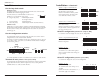
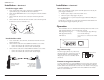
Install the copper cable
1. Locate or build twisted-pair copper cables that are compliant with the
specifications on page 11 with RJ-45 connectors at both ends.
2. Ensure that the MDI/MDI-X switch is set according to the network conditions
(see page 3).
3. Connect the RJ-45 connector at one end of cable to the RJ-45 port on the
device.
4. Connect the RJ-45 connector at the other end of the cable to the RJ-45 port on
the other device (switch, workstation, etc.).
RJ-45 port
on the other device
(switch, work station, etc
.)
RJ-45 port
on the media
converter
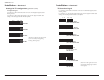
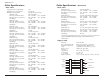
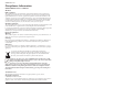
Install the fiber cable
1. Locate or build fiber cables with male, two-stranded TX to RX connectors
installed at both ends.
2. Connect the fiber cables to the local SSDTF10xx-10xDevice as described:
• Connect the male TX cable connector to the female TX port.
• Connect the male RX cable connector to the female RX port.
3. Connect the fiber cables to the remote SSDTF10xx-10xDevice as described:
• Connect the male TX cable connector to the female RX port.
• Connect the male RX cable connector to the female TX port.
Connect fiber cable
to media converter
as shown.
Connect fiber cable
to other device
(media converter,
hub, etc.) as shown
RX
TX
RX
TX
9
Operation
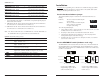
After installation, the device should function without operator intervention. Use the
status LEDs to monitor the device operation in the network.
SDC (Signal Detect/Copper) ON = the twisted-pair copper link is up.
SDF (Signal Detect/Fiber) ON = the fiber link is up.
PWR (Power) ON = the device is connected to external
power.
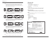
Dry-contact relay
The RJ-45 copper port has a dry-contact relay
that opens if the power, signal detect/copper, or
signal detect/fiber are lost. The operational
rating on pins 3 and 6 are 0-30 VDC, 100 mA
(maximum).
Remote management function
A remote, stand-alone device (revision SSDTF10xx-105 or higher) can be managed
when connected to a local CSDTF10xx-105 Device. Please note that in a managed
network, both the local and remote Devices must be set to “software” mode (see page
3). For more information, see the SNMP section in the CSDTF10xx-10x manual
online at: www.transition.com
Fiber
SDF
SDC
PWR
TX
RX
CL
FL
UTP/STP
Installation -- Continued
Power the device
Note: The external power supply provided with this product is UL listed by the
power supply’s manufacturer.
1. Install the power adapter cord to the back of the device.
2. Connect the power adapter plug to AC power.
3. Verify that the device is powered by observing the illuminated LED power
indicator light.
For DC power, consult the user’s guide for the Transition Networks SPS1872-xx
DC external power supply for powering the device.
Relay
3
6
RJ-45 Connector