1.
Verify connectivity between the two access points before mounting. Aside from the reconfigured WDS bridge settings, the TEW-740APBO access points will also be configured with the following default stings: TEW-7A0APBO #1 Mode: WDS Mote P Address: 192.168.10.50 Net mask (Subset Mask: 265.266.265.0 IP Gateway (Default Gateway): 192.168.10.1 Primary DNS: 192.168.10.1 TEW-740APRO #2 Mode: WDS Mode IP Address: 192.168.10.51 Net mask (Subset Mask): 255.255.255.0 P Gateway (Default Gateway: 192.168.10.
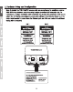
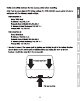
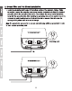
2. Removal the tab on the far left by gentry bending It back and forth until the tab I8 removed. ‘This wil crests the opening for a R-45 network cabs to ba routed through. 3. Using a network cabs, connect one end of the cable to the LAN (PoE} port and push the cable Into the cable guide on the far left, then through the opening that was created In the previous step.
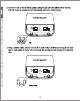
4, Connect the other end of the network cable to the P+DATA OUT port on the included PoE Injector. 5. Connect the Included power adapter to the PoE Injector POWER IN on the Included PoE Injector. 8. Plug the connected power adapter into a power outset. 7. Confirm the devices s powers on through the LED Indicators. Mote: Repeat Steps 1-7 to power on and connect the second access point. 8. Assign a strict IP address to your computer's network adapter in the subset of 192.168.10.x (6.9.192.168.10.
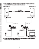
11. Make sure both access points are powered on approximately apart from one another with front of access points directly phasing aah other. TEW-740APBO 1 TEW-740APBO #2 12. To versify connectivity on your computer, open a command prompt or terminal application ‘window and types In the following commands.
Note: In Windaws®, you can use the Command Prompt application and in Mac®, you san Terminal application to run the commands for connectivity testing. ping 182.168.10.50
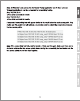
3. Ground Wire and Pole Mount Installation 1. Locate the grounding point located in the bosom section of the enclosure, Using a Phillips screwdriver, remove the grounding point screw (counter clockwise) and attach the Included grounding wire to the grounding point craw. Then reattach the ground screw (clockwise) along with the grounding wire. After installing the pounding wire, remove another tab on the enclosure by gently bending back and forth until the tab Is removed.
2. Re-Install the cover by lining up the guldens Info the notches as shown and push the cover down until the cover cps In and s secure. After reinstalling the cover, Insert the Included rubber seal in opening as show. 1 = 3. Insert the Included fasteners through the holes located at the back of the access point. 4.Wrap the fasteners around the polo whets the access points will ba Installed. On the fasteners, insert the open end it the locking mechanism and pull tight until the access point Is secured. 5.
FCL Statement ‘This equipment has been tested and found 1o comply with the limits for a Class B digital device, pursuant to part 15 of the FCC Rules. Thea limits ars designed to provide reasonable protection against harmful Interference In a residential Installation. This equipment generates, uses and can radiate radio frequency energy and, if not installed and used in accordance with the instructions, may cause harmful interference to radio communications.