TABLE OF C ONTENTS ABOUT THIS GUIDE ................................................... 3 INTRODUCTION ............................................................ 4 FEATURES AND BENEFITS .................................................. 5 UNPACKING THE PACKAGE ................................................ 7 SYSTEM REQUIREMENT ..................................................... 8 COMPONENTS GUIDE ......................................................... 9 HARDWARE INSTALLATION ........................
VIEW VIDEO – ACTIVEX MODE ....................................... 64 VIEW IMAGE – JAVA MODE ............................................. 65 IPVIEW PRO .................................................................. 67 INSTALLATION ................................................................. 67 GETTING STARTED........................................................... 71 USING IPVIEW PRO ......................................................... 74 CONFIGURING THE SYSTEM .............................
A BOUT T HIS G UIDE This manual provides instructions and illustrations on how to use your Camera, includes: z Chapter 1, Introduction, provides the general information on the camera. z Chapter 2, Hardware Installation, describes the hardware installation procedure for the camera. z Chapter 3, Security, explains the security feature of the camera. z Chapter 4, Application of the Camera, provides the illustrations of the camera’s applications.
1 I NTRODUCTION Thank you for purchasing TV-IP100-N/ TV-IP100W-N Camera, a camera device that can be directly connected to an Ethernet or Fast Ethernet network. TV-IP100W-N supports additional wireless transmission based on the IEEE 802.11b/g standard. Compared to the conventional PC Camera, the Camera features a built-in CPU and web-based solutions that can provide a costeffective solution to transmit real-time high-quality video images for monitoring.
Features and Benefits Ease To Use The TV-IP100-N/TV-IP100W-N (Wireless) Camera is a standalone system with built-in CPU requiring no special hardware (such as PC frame capture cards) or software required. The Camera supports both ActiveX mode (for Internet Explorer users) and Java mode (for Internet Explorer and Netscape Navigator users). Once you have a valid IP address, just connect it and you can view the image from your camera.
Intranet or Internet. Users are also allowed to monitor the image, and take snapshots. Broad Range of Applications With today’s high-speed Internet services, the camera can provide the ideal solution for live video images and audio sounds over the Intranet and Internet.
Unpacking the Package Unpack the package and check all the items carefully. One TV-IP100-N/ TV-IP100W-N One Detachable Antenna ( TV-IP100W-N only) One Multi-Language Quick Installation Guide One Driver & Utility CD-ROM with User’s Guide One External Power Adapter (5VDC 2.5A) One RJ-45 Network Cable One Camera Mounting Bracket If any packaging content is damaged or missing, please contact your local dealer immediately.
System Requirement Networking Local Area Network: 10Base-T Ethernet or 100Base-TX Fast Ethernet. Wireless Local Area Network ( TV-IP100W-N Only): IEEE 802.11b/g Wireless LAN. Accessing the Camera For Web Browser Users Operating System: Microsoft® Windows® 98SE/ME/ 2000/XP/Vista CPU: 300MHz or above Memory Size: 32MB (64MB recommended) Resolution: 800x600 or above Microsoft® Internet Explorer 5.0 or above; Netscape 6.
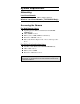
Components Guide This section provides the information of camera and explains the function of each component.
1. Screw Hole It located on the top/bottom panel of the camera. The screw hole is used to connect the camera stand onto the camera by attaching the screw head on the camera stand into the screw hole of the camera. 2. Power LED A steady BLUE light indicates that the Camera is powered on. 3. Link LED A steady ORANGE light indicates that the camera has good connection to LAN/WLAN. It begins flashing to indicate the camera is receiving/sending data from/to the LAN/WLAN. 4.
6. 10/100 Ethernet LAN Port This RJ-45 connector is used to connect the 10Base-T Ethernet or 100Base-TX Fast Ethernet network (which should be Category 5 twisted-pair cable). The port supports the N-Way protocol & Auto-MDIX, it allowing the camera automatically detects or negotiates the transmission speed of the network. 7. Detachable Antenna ( TV-IP100W-N) The detachable external antenna allows you to adjust its position to obtain the maximum signal.
2 H ARDWARE I NSTALLATION Attaching the Camera to the Stand The Camera comes with a camera stand, which has a swivel ball screw head that can be attached to the top/bottom of camera’s screw hole. Attach the camera to the stand and station it for your application. There are three holes located in the base of the stand allowing the Camera to be mounted on the ceiling or any wall securely.
Connecting the Ethernet cable Connect an Ethernet cable to the RJ-45 Port, and then connect it to the network. Attaching the Power Supply Attach the power supply to the power connector of the Camera. Then connect the power supply to the wall outlet.
3 S ECURITY To ensure the highest security and prevent unauthorized usage of the camera, the administrator has the exclusive privilege to access the System Administration for settings and control requirements to allow users the level of entry and authorize the privileges for all users. The camera supports multi-level password protection. Access to the camera is strictly restricted to define the user who has a “User Name” and “User Password” that is assigned by the administrator.
4 A PPLICATION The TV-IP100-N/ TV-IP100W-N Camera can be applied in wide variety of applications, including: z Monitoring of local and remote places and objects such as construction sites, hospitals, parks, schools and day-care centers through the use of a web browser. z Capture single frame images from the IPView Pro application. z Configure the camera to upload image or send-mail messages with a single frame image.
Application Diagrams of the Camera Home or Business Applications 16
5 U SING THE UTILITY This chapter describes the software utilities for the IP camera, including how to set up your Camera with the utility. The Setup Wizard is designed with a user-friendly interface that allows you to set up the Camera easily. Auto-Run Installation Insert the Installation CD-ROM into your computer’s CD-ROM drive to initiate the Auto-Run program.
• Setup Wizard – click to launch the Setup Wizard program which is helpful to set up the IP Camera configuration easily and quickly. • IPView– click to install IPView program to control and navigate the camera. Please refer to the chapter 6 section for detailed information on installing the utility. • Xplug Control – click to launch Xplug control. Please refer to Trouble Shooting section for more detail installation.
Setup Wizard To avoid IP address conflicts in your network, you can use Setup Wizard to change the related settings of your Camera (such as the IP address) after finishing hardware installation. Installing Setup Wizard 1. Click Setup Wizard from the Auto-Run menu screen. The InstallShield Wizard will appear. Click Next > when the Welcome to the InstallShield Wizard for Setup Wizard screen appears. 2. Click Yes > to accept the End User License Agreement.
3. Click Browse to choose the desired destination location. By default, the destination location is C:\Program Files\Setup Wizard. Then click Next >. 4. The InstallShield Wizard starts to install the software. A status screen appears indicating the progress of the installation. 5. When the InstallShield Wizard Complete window appears, click Finish. .
After installing the utility, the application program for the camera is automatically installed to your computer, and creates a folder in Start\Programs\SetupWizard. Using Setup Wizard This section describes the operation of Setup Wizard. To launch the Wizard: 1. Click Start -> Programs -> Setup Wizard, and then click SetupWizard. 2. The window below will appear. The IP Camera Setup Wizard will automatically search for IP Cameras within the network and assign an available IP address for your camera.
Double click the found Device. The Windows Internet Explorer will ask you for User name and Password. Please type in default “admin” in both field and click OK. After this, you can access this camera. (Go to page 28) Wizard - If you want to assign a dedicate IP address, you can change the IP address setting.
- Select IP Camera, then click Wizard - If the Camera’s default IP is different than your network’s IP subnet, the Wizard will help you to search for a proper IP address. Click YES to change the IP address. - Use the DHCP assigned IP address or manually set the IP address. The IP address must match your network’s IP subnet. Then click OK. Note: Please note the IP address.
your local area network. Your IP Address might look different than the example above. - Assign Admin ID & Password here. By default, the Admin ID and Password are “admin”. You can select “Change” to type new Admin ID & Password. Then click Next (Right Arrow) - Setup the Primary DNS or Secondary DNS if necessary.
- Wireless Configure setting. (For TV-IP100W-N only) Select the connection mode, type in your wireless network’s SSID, select the security mode and then click Next (Right Arrow) - Select the Encryption Mode, key format and enter the key. Then click Next (Right Arrow). - Review all the setting then click restart.
Search - This button will search the available camera(s) within the network. Link - This button links to the web configuration section.
About - This button displays Setup Wizard information.
6 U SING THE C AMERA You can access and manage the camera through: 1) a web browser, and 2) the enclosed software IPView Pro. This chapter describes the Web Configuration Utility, and provides the instructions on using the camera with a web browser. Web Configuration Utility Whenever you want to configure the camera, open your web browser (e.g. Internet Explorer in this manual), and type the assigned DHCP IP address which can be found by using Setup Wizard in the Address bar and press [Enter].
Camera IP address Pre-view area Welcome Screen of the Configuration Utility After the default IP address is entered from the browser, the Camera Welcome screen will appear with a still image.
Administration On the Welcome screen of the Configuration Utility, click Administration to enter the administration window that contains the settings required for the camera in the left hand menu bar, including Status, Configuration, Tools and Help. TIP: Click Save to store the settings, or Cancel to abandon, or Refresh to reload the status. Click Home on the top menu bar will link to the Welcome window. Administration J Status The Status window contains the information of your configuration.
System Click the System item in the left column to display the device status of your camera. - Device Status: The information about the camera, including the Camera Name, Location, Model, Firmware Version, MAC Address and IP Address, can be found in this field.
- Ethernet Status: You can monitor the networking status in this field, including the Link (network connection), Speed, and the Duplex mode. Video Click the Video item in the left column to display the video configuration of your camera. - Video Status: The video configuration about the camera, including the Video Resolution, Compression Rate, Frame Rate, Frame Size and IP Address, can be found in this field.
Wireless (for TV-IP100W-N only) Click the Wireless item in the left column to display the information of the wireless LAN. - Wireless Status: The items in this field display the information of the wireless LAN, such as the Connection Mode (Infrastructure or Ad-Hoc), Link, SSID, Channel, Transmission Rate, and WEP Encryption.
Network Click the Network item in the left column to display the information of the LAN. - Network Status: The items in this field display the information of the LAN, such as the IP Address, Subnet Mask, Default Gateway, Primary DNS Address, Secondary DNS Address, Dynamic DNS, Secondary HTTP Port, and UPnP.
Active Users Click the User item in the left column to display the user(s) information. - Active Users: The items in this field display the user(s) information, including the user(s) IP address, Name, and DateTime.
Administration J Configuration The Configuration window contains commands for settings that are required to input key details to setup the camera for operation. Click Configuration in the top menu bar and the Configuration window will appear as below: System Click the System item in the left column to setup the basic configuration of your camera.
- System Setting: In this field, you can configure the basic information of your camera. • Camera Name: This field is used to enter a descriptive name for the device. The default setting for the Camera Server Name is CS-xxxxxx, where xxxxxx is the last six digit of the MAC Address. The maximum length is 32 (printable ASCII). • Location: This field is used to enter a descriptive name for the location used by the camera (optional).
It is highly recommended to set your own Admin ID and Admin Password as soon as possible to enable security option for the Camera to function. • LED Control: This option allows user to setup the LED illumination as desired. This feature provides the flexibility when surveillance activity is ON. There are three options as follows: Normal OFF Dummy Power - Steady On of the LED indicator. Link - Steady On of the LED indicator. When WLAN activity is present the LED indicator will flash steadily.
Video Click the Video item in the left column to setup the image configuration of your camera. - Video Setting: In this field, you can configure the basic information of your camera. • Video Resolution: Select the desired video resolution format, including 160x120, 320x240 (default) and 640x480. • Compression Rate: Select the desired compression rate with five levels from Very Low to Very High. Higher video compression rate will generate more compact file size with less video quality and viseversa.
• Brightness Control: Adjust the brightness level with default setting at 64. • Contrast Control: Adjust the contrast level with default setting at 64. • Saturation Control: Adjust the saturation with default setting at 64. • Light Frequency: Adjust the light frequency to suit your area of operation from the options either 50 Hz or 60 Hz (default).
Wireless (for TV-IP100W-N only) Click the Wireless item in the left column to setup the wireless LAN configuration of your camera.
- Wireless Interface • Connection Mode: Use this option to determine the type of wireless communication for your camera. There are two choices of Infrastructure mode and AdHoc mode. The default setting is Infrastructure. • SSID: The SSID (Service Set Identifier) is the name assigned to the wireless network. It will auto-detect and display the SSID of wireless network connected in this box (it displays default initially).
To connect the camera to an Ad-Hoc wireless workgroup, make sure to set the same wireless channel and SSID to match with the PC/Notebook’s configuration for direct wireless communication. • Wireless Channel: This pull-down menu provides the wireless channel for communication. A "channel" is a range of frequencies to be used in communication between the camera and access point in Infrastructure mode, or the camera and PC/Notebook in Ad-Hoc mode.
• WEP Encryption: Wireless network communications can be intercepted easily. WEP (Wired Equivalent Privacy) is an encryption method specified by the IEEE 802.11g standard to make any intercepted communications extremely difficult to interpret by unauthorized parties. The default setting for this option is Disable. • WEP Key Length: Select the proper setting for WEP Encryption. In general, a larger key length creates a stronger cipher. The default is 64-bits.
Wireless Camera will automatically pad your input to a bit count of 64 or 128. • Encrypt Data Transmissions Using: Use this pulldown menu to decide to use Key 1, 2, 3 or 4 for encryption). • WPA-PSK/WPA-PSK2: This is a special mode designed for home and small business users who do not have access to network authentication servers. In this mode, the user has to manually enter the starting password in their access point or gateway, as well as in each PC on the wireless network.
Network Click the Network item in the left column to setup the LAN configuration of your camera. - TCP/IP: The items in this field display the information of the wireless LAN, such as the Connection Mode (Infrastructure or Ad-Hoc), Link, SSID, Channel, Transmission Rate, and WEP Encryption.
Fixed IP – You can select this option and enter the IP address directly. The default settings are: • IP Address – 192.168.10.30 • Subnet Mask – 255.255.255.0 • Default Gateway – 0.0.0.0 Dynamic Address (DHCP) – If your network uses the DHCP server, select this option. According to this setting, the camera will be assigned an IP address from the DHCP server automatically. Every time when the camera starts up, please make sure that the DHCP server is set to assign a static IP address to your camera.
• UPnP: UPnP is the architecture for pervasive peer-topeer network connectivity of intelligent appliances, wireless devices, and PCs of all form factors. Check the Enable option to enable the function of your camera. User Click the User item in the left column to add, edit and delete users for your camera.
to users by selecting Enable or Disable. The default setting is No. - Define Users: Use this field to add or delete users for your camera. • Add User: Enter the user name in this box, and enter the user’s password assigned by the administrator. The maximum password length is 8 (printable ASCII). The administrator has the authority to give permission for the privilege to control the Upload/E-mail Video control to the users by selecting Yes or No to activate the Upload/E-mail Video.
DateTime Click the DateTime item in the left column to setup time and date for your camera, providing correct information for the remote users who might be thousands of miles away from the camera’s location. - Date & Time: You can set up time and date manually or automatically by selecting the Synchronized with Time Server option. • Synchronized with Time Server: Select this option and the time will be based on GMT setting. The time will be synchronized every 10 minutes.
TimeZone – Select the time zone for the region from the pull-down menu. • Set Manually: Select this option to set the time manually. The system administrator must enter the date and time in the respective field manually.
52
Upload Click the Upload item in the left column to setup configuration for FTP server, time schedule and manual operation. - FTP Server: This field contains the following six basic settings for your FTP server.
• Host Address: The IP Address of the target FTP server. • Port Number: The standard port number for the FTP server is Port 21, and it’s also the default setting. If the FTP server uses a specific port, please confirm the IT manager. • User Name: Enter the user name in this field. • Password: Enter the user password in this field to login the FTP server. • Directory Path: Enter an existing folder name in this field, and the images will be uploaded to the given folder.
- Manual Operation: When you click the Upload Video button in view video screen, it will start to upload the image. The setting refers to Base File Name and File information above. E-mail Click the E-mail item in the left column to setup configuration for E-mail account, time schedule and manual operation settings.
- E-mail Account: This field contains the following six basic settings for your FTP server. • SMTP Server Address: SMTP (Simple Mail Transfer Protocol) is a protocol for sending e-mail messages between servers you need to input the mail server address in this field. • Sender e-mail Address: Enter the e-mail address of the user who will send the e-mail. • Receiver e-mail Address: Enter the e-mail address of the user who will receive the e-mail. • User Name: Enter the user name in this field.
Administration J Tools The Tools window contains commands for restarting the camera. Click Tools in the top menu bar and the Tools window will appear as below: FTP Server Test Click the FTP Server Test item in the left column to test your FTP server.
E-mail Test Click the E-mail Test item in the left column to test your e-mail account. - Test E-mail Account: Click the Test button to test the e-mail account you provided.
Reset Do you really want to reset this device? Click the YES button from this option, and you can restart the camera just like turning the device off and on and saved settings are retained. If you do not want to reset the camera, exit this window without clicking YES. Factory Reset Do you really want to factory reset this device? Click the YES button from this option, and you can resume all factory default settings for the camera.
Firmware Upgrade When new firmware is available, you can upgrade it through this window. Click the Browse… button to point to the firmware file (XXX.bin), and then click Update to start upgrading.
Backup Click the Backup item in the left column to backup the current configuration. - Backup Device Configuration to File: Do you really want to backup the configuration to file? Click the Backup button from this option, and you can save the current configuration to file.
computer. Click the Browse… button to point to the file, and then click Restore to start restoring. Administration J Help The Help window provides the basic information of the camera.
About Displays the camera’s model name and version. Once the configuration is completed, click Home to return to the Welcome screen and select the desired View Video option either through ActiveX Mode or Java Mode as described in the next section. Then, position the camera to the desired location appropriately for your purpose. Followed by adjustment of the camera focus, done manually by turning the lens clockwise or anti-clockwise to the desire image quality.
View Video – ActiveX Mode To view video images from the browser, click View Image – ActiveX Mode from the Welcome screen to access the video images from Internet Explorer as illustrated below: Camera Name Camera Name: The Camera name will be displayed when the Camera Name field is entered in the Web Configuration setting under Configuration. In the View Video – ActiveX Mode, you are allowed to use the Upload Video and E-mail Video options.
View Image – Java Mode To view video images from the browser, click View Image – Java Mode from the Welcome screen to access the video images from Internet Explorer or Netscape browser as illustrated below: Camera Name Date and Time Camera Name: The Camera name will be displayed when the Camera Name field is entered in the Web Configuration setting under Configuration. Date and Time: The date/time of the camera will be displayed here.
In the View Video – Java Mode, you are allowed to use the Upload Video and E-mail Video options. Simply click the desired selection ON or OFF to utilize the options for each of the functions. NOTE: • Please refer to the appendix on how to install ActiveX, including 1.) install to the Web Server, and 2.) install to your Local PC. • Please download Sun Microsystems Java Runtime Environment (JRE) to view image in JAVA mode.
7 IPV IEW PRO This chapter describes the IPView PRO, which is a powerful software application designed with a user-friendly interface for ease of control and navigation requirements. Installation Step 1 Insert the CD-ROM into the CD-ROM drive to initiate the autorun program.
Step 2 Click the IPView item to activate the InstallShield Wizard. Click Next in the welcome screen. Step 3 Read and accept the License Agreement; then, click Yes.
Choose the destination location. If no specific requirement, leave the default setting and click Next. Step 5 The InstallShield Wizard starts to install the software, and the progress bar indicates the installation is proceeding.
Step 6 Click Finish to complete the installation.
Getting Started This section describes the User Interface of IPView Pro, with detailed procedures for using the application. To launch IPView Pro, click Start > Programs > IPView Pro > IPView Pro. The main screen will appear as below: NOTE: IPView Pro requires the system’s resolution setting up to 1024x768. Please configure the resolution to 1024x768 or higher; otherwise, it may shows incomplete screen when launching the program.
Item Feature NO. 1 2 Item Date/Time Description Show current date/time. Status Mode Window Show the camera’s status in this window. Click the Change Status Mode button ( ) on the right lower corner of the window to change the display mode: Camera list mode Camera information mode 3 View Window Show the camera’s view in this window. 4 Connect/ Disconnect Click to connect/disconnect the camera. 5 Rotate image angle Click to rotate the image shown in the View Window.
Show six cameras in View Window with the first one as the major view. Show eight cameras in View Window with the first one as the major view. Show nine cameras in View Window. Show ten cameras in View Window with the first two as the major views. Show thirteen cameras in View Window with the first one as the major view. Show sixteen cameras in View Window. Show the selected camera in full screen view. Enable displaying the video views in circles. 10 Key Lock Button Click to lock/unlock the camera.
Using IPView Pro Adding a Camera To add a camera: 1. Click the System Configuration button to enter the System Configuration. If you are not sure of the camera’s IP address, you can click Search to search the available camera(s) within the network.
2. Select the camera you want by highlighting it, and then click Add Camera. The camera is added. Click the Add Camera button. The camera found within the network. 3. Click Save, and then click the System Configuration button to return to View Window. The selected camera’s video will be displayed now. You can click Save as to save the selected cameras into the desired path and the selected cameras can be reloaded by load button.
Alternately, you can add a camera by entering the its IP address directly: 4. Select the Input IP tab. The camera is added. Click the Add Camera button. Enter the camera’s IP address and Port. 5. Enter the camera’s IP address (default: 192.168.10.30) and Port (default: 80), and then click Add Camera. 6. Click Save, and then click the System Configuration button to return to View Window. The selected camera’s video will be displayed now.
Removing a Camera To remove the camera from the list: 1. Select the camera you want to remove. 2. Click Delete Camera.
Viewing a Camera From the View Modes of the panel, you can select one-camera mode or other modes to display your video. IPView Pro allows a maximum of 16 cameras for viewing. For example, if you use only one camera, select one-camera mode ( ), and the View Window will display the view as figure 1. If there are four cameras, select four-camera mode ( ), and the View Window will display the view as figure 2.
Recording Video IPView Pro allows you to record the video clip and save it in your computer through the following methods: Manual Record, Schedule Record, and Motion Record. When you click the Record button and select Manual Record, it will start recording. Click the button again to stop. If you select Schedule Record or Motion Record, the system will record the video clip according to the settings in System Configuration.
Select the recorded file in the computer, and then click OK. Configuring the System Clicking the System Configuration button on the panel allows you to configure the system settings, and the System Configuration Screen will appear in the View Window as shown below. Once configured, click Save to save the settings, and then click the System Configuration button again to exit configuration.
System Configuration Screen Camera Configuration In this field, you can add/delete the camera (as described in the previous section). Also, you can configure the following settings: Web Configuration In the top low, selecting the Administration item will launch the Web Configuration Utility in View Window.
You can configure these settings according to the description in Chapter 5, Using the Camera. Click Back to exit the Web Configuration Utility. Motion Configuration-1 The Motion Configuration-1 item provides the commands for motion detection control. Before configuring, you should select one camera from the pull-down menu. Select one camera. Select Custom region. Region 1. Region 2. - Detect Region: • Full picture – When you select this option, the camera will monitor the whole area.
• - Custom region – Click Add Region, and then use mouse to draw an area in the view screen; when some motion detected within the area, the camera starts recording automatically. You can set multiple areas in the view screen. Click Delete Region to remove the area selected. Click Clear All Region to remove all areas in the view screen. Sensitivity Level: Move the slide bar to adjust the sensitivity level for detecting motion to record video.
- - - Invoke Alarm: Select this option to enable alarm when some motion detected by the system. Send e-mail: When this option is checked, click the Mailing Configuration in the left column to enter the required information (see the following section). Play music: You can use the music file to alert the event. Click Browse music file to select the desired music, and set the Interval time. Trigger1 active: You can check this option to set the Trigger-On holding time.
Tools The Tools item allows you to configure to the alarm and e-mail setting. - - - Reset: Restore the original setting of your camera. Do you really want to reset this device? Click Yes in the pop-up dialog box to confirm. Factory Reset: Restore the factory default settings of the camera. Do you really want to factory reset this device? Click Yes in the pop-up dialog box to confirm. Update Firmware: When new firmware is available, you can upgrade it using this option.
Mailing Configuration When Motion Detection function is enabled and the Send e-mail option is checked, you should enter the required information in the respective fields. - Mail Server: Enter the mail server address that is used to send your e-mail. Mail From/To: Enter the sender’s/receiver’s e-mail address. Subject: Enter the title of the e-mail. User Name/Password: Enter the user name/password to login the mail server.
Proxy Server Check the Proxy Server option and enter the required settings in the Address and Port boxes to enable and use the Proxy Server function.
Recording Configuration In this field, you can configure the storage settings. - Log Storage: • Reserved HDD Space For MS-Windows OS – You can reserve 500 MB to 10000 MB hard disk space for the program. • Each Recording File Size – If the recorded video files reach the file size limit, video images will be recorded into another file automatically. The available settings are from 10 MB to 50 MB. • Storage List – The destination folder to save the recorded video file can be specified here.
- - change the current path setting; click Add to add a new destination folder; click Delete to remove a selected path setting. Please note that you are not allowed to delete a path setting if there is only one setting in the list. Recycle: You can check this option to clear the files when the unreserved space of your hard disk is filled. The available settings are from 200 MB to 50000 MB.
- Date Mode: First, select the camera desired from the pulldown menu. Then, setup the time in the Start/Stop fields. Click Add to add the recording schedule to the list. Click Save to save the settings.
Weekday buttons. - Week Mode: First, select the camera desired from the pulldown menu. Then, setup the time in the Start/Stop fields, and select the weekday from the buttons. Click Add to add the recording schedule to the list. Click Save to save the settings. Others When multiple cameras connected, this option allows the system to display these views as the main view in circles according to your time settings. The range of Time interval of scan is from 1 to 20 seconds.
Log List This filed displays the user(s) information, which includes the Date, MAC address, and the brief description of events.
Account This filed allows you to set the Admin ID and Admin Password. You can also check the Login password check option to secure your camera by checking the login password.
94
About This filed provides information of the software application.
8 A PPENDIX A Frequently Asked Questions Camera Features Q: What is an Internet Camera Server? A: The Camera is a standalone system connecting directly to an Ethernet or Fast Ethernet network and supported by the wireless transmission based on the IEEE 802.11b/g standard. It is different from the conventional PC Camera, the Camera is an allin-one system with built-in CPU and web-based solutions providing a low cost solution that can transmit high quality video images for monitoring.
the transmission speed will slow down when many users are logged on. Q: What algorithm is used to compress the digital image? A: The Camera utilizes the JPEG image compression technology providing high quality images for users. JPEG is adopted since it is a standard for image compression and can be applied to various web browser and application software without the need to install extra software.
A: The Camera is not weatherproof. It needs to be equipped with a weatherproof case to be used outdoors and it is not recommended. Q: What network cabling is required for the Camera? A: The Camera uses Category 5 UTP cable allowing 10 Base-T and 100 Base-T networking. Q: Can the Camera be setup as a PC-Cam on the computer? A: No, the Camera is an Camera used only on Ethernet and Fast Ethernet network and wireless transmission (Wireless only for TV-IP100W-N).
B PING Your IP Address The PING (Packet Internet Groper) command can determine whether a specific IP address is accessible by sending a packet to the specific address and waiting for a reply. It can also provide a very useful tool to confirm if the IP address conflicts with the Wireless Camera over the network. Follow the step-by-step procedure below to utilize the PING command. However, you must disconnect the Wireless Camera from the network first. Start a DOS window. Type ping x.x.x.x, where x.x.x.
C Trouble Shooting Q: I cannot access the Camera from a web browser. A1: The possible cause might be the IP Address for the Camera is already being used by another device. To correct the possible problem, you need to first disconnect the Camera from the network. Then run the PING utility (follow the instructions in Appendix B - PING Your IP Address). A2: Another possible reason is the IP Address is located on a different subnet.
A3: Other possible problems might be due to the network cable. Try replacing your network cable. Test the network interface of the product by connecting a local computer to the unit, utilizing a standard Crossover (hub to hub) Cable. If the problem is not solved the Camera might be faulty. Q: Why does the Power LED not light up constantly? A: The power supply used might be at fault. Confirm that you are using the provided power supply DC 5V for the camera and verify that the power supply is well connected.
Q: Why does the Wireless Camera work locally but not externally? A1: Might be caused from the firewall protection. Need to check the Internet firewall with your system administrator. A2: The default router setting might be a possible reason. Need to double check if the configuration of the default router settings is required.
A2: There might be wireless transmission interference make sure there are no other wireless devices on the network that will affect the wireless transmission. Q: There is poor image quality, how can I improve the image? A1: A probable cause might be the incorrect display properties configuration for your desktop. You need to open the Display Properties on your desktop and configure your display to show at least 65’000 colors for example at least 16bit.
D Time Zone Table 104
105
E Xplug Control Installation Installation to Web Server Important Information It is highly recommended to install the Xplug Control application to the Web Server for IE 5.0. It must be installed to a Public Domain with Fixed IP address. 1. Installation: Copy the “xplug.ocx” file to any WEB Server table. 2. Setting (Configuration): From the Web Configuration menu select “System” and under the “Loading ActiveX From” input web server location (http://www.web server location.com/).
Installation to Local PC Insert the CD-ROM into the CD-ROM drive to initiate the autorun program. Once completed, a menu screen will appear as below: To install Xplug Control, click the “Xplug Control" button to activate the installation procedure for the plug-in program. Once executed, a prompt will appear requesting the input of the desired language selection. Make the desired selection and click “OK” to continue.
The Welcome screen will appear. Click the “Next” button to proceed with the installation. The License Agreement prompt will appear as below. Read the details carefully and click the “Yes” button to continue with the installation procedure.
Click the “Finish” button to complete Setup of the Xplug Control Utility program for the Wireless Camera.
F Adjust Camera Focus To adjust the focus of the lens, you need to turn the lens slowly in either clockwise or anti-clockwise direction until the desired image appears. DO NOT over turn the lens in either of the directions, as it will be out of focus. NOTE: You can further adjust the Wireless Camera's image quality through System Administration – Image of Web Configuration. Please refer to Web Configuration section for further details.
G Specification Video specification Resolution: 160 x 120, 320 x 240, 640 x 480 pixel Color CMOS sensor f: 6.0 mm, F: 1.
CPU: RAM: Flash ROM: OS: Power Supply: Power consumption: LED Indicator: RDC R2880 8MB 2MB RTOS DC 5V, switching type 5 Watt (1000mA x 5V) Power LED (Blue) Activity LED (Orange) Software Browser: Application Software: OS supported: Internet Explorer 5.0 or above; Netscape 6.0 or above IPView PRO Microsoft Windows 98SE/ME/ 2000/XP/Vista, Windows NT4.
H Glossary of Terms NUMBERS 10BASE-T 10BASE-T is Ethernet over UTP Category III,IV, or V unshielded twisted-pair media. 100BASE-TX The two-pair twisted-media implementation 100BASE-T is called 100BASE-TX. 802.11g An IEEE standard for wireless local area networks. It offers transmissions speeds at up to 54 Mbps in the 2.4GHz band. of A Access point It is the hardware interface between a wireless LAN and a wired LAN. The access point attaches to the wired LAN through an Ethernet connection.
ARP Address Resolution Protocol. ARP is a protocol that resides at the TCP/IP Internet layer that delivers data on the same network by translating an IP address to a physical address. AVI Audio Video Interleave, it is a Windows platform audio and video file type, a common format for small movies and videos. B BOOTP Bootstrap Protocol is an Internet protocol that can automatically configure a network device in a diskless workstation to give its own IP address.
addresses to devices on a network. With dynamic addressing, a device can have a different IP address every time it connects to the network. In some systems, the device's IP address can even change while it is still connected. DHCP also supports a mix of static and dynamic IP addresses. This simplifies the task for network administrators because the software keeps track of IP addresses rather than requiring an administrator to manage the task.
Ethernet The most popular LAN communication technology. There are a variety of types of Ethernet, including 10 Mbps (traditional Ethernet), 100 Mbps (Fast Ethernet), and 1,000 Mbps (Gigabit Ethernet). Most Ethernet networks use Category 5 cabling to carry information, in the form of electrical signals, between devices. Ethernet is an implementation of CSMA/CD that operates in a bus or star topology.
H HEX Short for hexadecimal refers to the base-16 number system, which consists of 16 unique symbols: the numbers 0 to 9 and the letters A to F. For example, the decimal number 15 is represented as F in the hexadecimal numbering system. The hexadecimal system is useful because it can represent every byte (8 bits) as two consecutive hexadecimal digits. It is easier for humans to read hexadecimal numbers than binary numbers. I IEEE Institute of Electrical and Electronic Engineers.
format used to route the information. Your Internet service provider controls the IP address of any device it connects to the Internet. The IP addresses in your network must conform to IP addressing rules. In smaller LANs, most people will allow the DHCP function of a router or gateway to assign the IP addresses on internal networks. IP address IP address is a 32-binary digit number that identifies each sender or receiver of information that is sent in packets across the Internet. For example 80.80.80.
L LAN Local Area Network a computer network that spans a relatively small area sharing common resources. Most LANs are confined to a single building or group of buildings. N NAT Network Address Translator generally applied by a router, that makes many different IP addresses on an internal network appear to the Internet as a single address. For routing messages properly within your network, each device requires a unique IP address. But the addresses may not be valid outside your network.
NWay Protocol A network protocol that can automatically negotiate the highest possible transmission speed between two devices. P PING Packet Internet Groper, a utility used to determine whether a specific IP address is accessible. It functions by sending a packet to the specified address and waits for a reply. It is primarily used to troubleshoot Internet connections. PPPoE Point-to-Point Protocol over Ethernet.
for transferors the medium include token-passing and Carrier Sense Multiple Access with Collision Detection (CSMA/CD),implemented as token-ring, ARCNET, FDDI, or Ethernet. The Router Information Protocol (RIP),a part of the Transmission Control Protocol/Internet Protocol (TCP/IP) suite, forwards packets from one network to another using the same network protocol.
Station In LANs, a station consists of a device that can communicate data on the network. In FDDI, a station includes both physical nodes and addressable logical devices. Workstations, single-attach stations, dualattach stations, and concentrators are FDDI stations. Subnet mask In TCP/IP, the bits used to create the subnet are called the subnet mask.
ULP The upper-layer protocol refers to Application Layer protocols such as FTP,SNMP, and SMTP. User Name The USERNAME is the unique name assigned to each person who has access to the LAN. Utility It is a program that performs a specific task. UTP Unshielded twisted-pair. UTP is a form of cable used by all access methods. It consists of several pairs of wires enclosed in an unshielded sheath. W WAN Wide-Area Network.
Limited Warranty TRENDnet warrants its products against defects in material and workmanship, under normal use and service, for the following lengths of time from the date of purchase.
LAW, STATUTORY OR OTHERWISE, INCLUDING WARRANTIES OF MERCHANTABILITY AND FITNESS FOR A PARTICULAR PURPOSE. TRENDNET NEITHER ASSUMES NOR AUTHORIZES ANY OTHER PERSON TO ASSUME FOR IT ANY OTHER LIABILITY IN CONNECTION WITH THE SALE, INSTALLATION MAINTENANCE OR USE OF TRENDNET’S PRODUCTS.