TS2501 Wi-Fi Smart Thermostat Installation Guide
Table of Contents 1 Preparation - What is in the box? 5 - Tools needed for installation 6 - Accessories (Sold separately) 6 - Quick Start Guide for Homeowner Installation 7 - Quick Start Guide for Contractor Installation 8 - Precautionary measures 9 - Let's get started! 11 - With or without C-Wire? 12 2 Installation With a C-Wire - Step 1: Disconnect and label old thermostat wires 13 - Step 2: Remove old jumper wire 14 - Step 3: Unscrew old Mounting Plate 15 - Step 4: Replace with new Thermostat Mount
- Step 9: Disconnect and label old thermostat wires - Step 10: Unscrew old Mounting Plate - Step 11: Replace with new Thermostat Mounting Plate - Step 12: If the Trim Plate is used (Optional) - Step 13: Pull the labeled wires through the hole of the Mounting Plate - Step 14: Attach the Mounting Plate on the wall - Step 15: Connect the wires - Step 16: Set the jumpers on the back of your Thermostat - Step 17: Attach the Thermostat onto its Mounting Plate until it clicks - Step 18: Turn on the power - Install
Welcome! Thank you for choosing the TrickleStar TS2501 Wi-Fi Smart Thermostat. We are your smart partner in optimizing comfort and maximizing savings for your Heating, Ventilation, and Air Conditioning (HVAC) systems. You can now remotely control and monitor the heating and cooling systems in your home and business from anywhere. If you have any inquiries about TrickleStar products or need technical support, visit our website for tutorials, videos and Frequently Asked Questions (FAQ).
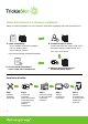
Preparation What is in the box? Thermostat with Mounting Plate Screws (4 pcs) Trim Plate Drywall plugs (4 pcs) Extra jumpers Wire labels Quick Start Guide 5
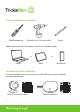
Tools neededed for installation Phillips screwdriver Drill with 3/16 in. (3.3 mm) drill bit Pencil Mobile devices with Wi-Fi connection (to access to TrickleStar Portal): or Laptop or Tablet Smartphone Accessories (Sold separately) For more information on these accessories, scan the QR code or visit our website at: www.tricklestar.
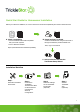
Quick Start Guide for Homeowner Installation Before you start the installation, be sure to check the Thermostat compatibility and create a Portal account. + A. Check compatibility - Is the TrickleStar Thermostat compatible with your HVAC system? - Is the C-Wire Kit needed? https://portal.tricklestar.com/tstat/compatibility B. Create and log in to Portal Create a Portal account using the QR code or through the website: portal.tricklestar.com Then, log in to the Portal. + C.
Quick Start Guide for Contractor Installation Before you start the installation, be sure to check the Thermostat compatibility and create a Portal account. + A. Check compatibility B. Create and log in to Portal Create a Portal account using the QR code or through the website: portal.tricklestar.com - Is the TrickleStar Thermostat compatible with your HVAC system? - Is the C-Wire Kit needed? https://portal.tricklestar.com/tstat/compatibility Then, log in to the Portal. + D.
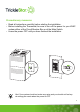
Precautionary measures • Read all instructions carefully before starting the installation. • Before installing the Thermostat, be sure to turn off the power for your HVAC system either at the Circuit Breaker Box or at the Main Switch. • Leave the power OFF until you have finished the installation. OFF OFF Hint: Your system should not make any noise and you should not feel any air exiting your vents when the power is OFF.
• Remove the front cover of your old thermostat from its base. • Your system is not compatible with the TrickleStar Thermostat if you see: - thick black wires with wire nuts. - the base on the old thermostat has “L1” and “L2” on the terminal blocks. - “120 - 240 V AC” or “High Voltage” labels. • The TrickleStar Thermostat is ONLY designed for 24 V AC with a total switching current of 3 A maximum.
Let’s get started! Before you start the installation, we recommend that you take a photo of the label attached at the bottom of your Thermostat. You may need to refer to the information when you connect your Thermostat to Wi-Fi via the TrickleStar Portal.
With or without C-Wire? The TrickleStar Thermostat supports installation for both with and without C-Wire, but the installation is a little different. Do you have a C-Wire connected to your old thermostat? Check the wires connected to the terminals on the base of your old thermostat. • If a wire is connected to the “C” terminal, then your system has a C-Wire to power your new TrickleStar Thermostat.
Installation With a C-Wire If your system has a C-Wire, it will power your new TrickleStar Thermostat. You do not need a C-Wire Kit (sold separately as an accessory). Step 1: Disconnect and label old thermostat wires Disconnect and label the wire from your old thermostat carefully, one wire at a time, using the wire labels provided. Make sure the wires do not fall back into the wall when released from the terminals and that the labels are fastened to the wires securely.
Step 2: Remove old jumper wire If the terminals on your old thermostat has a jumper wire between RH, RC or R, remove the jumper wire. Your new TrickleStar Thermostat does not need this jumper wire.
Step 3: Unscrew old Mounting Plate Unscrew the Mounting Plate of your old thermostat to remove it from the wall. When you remove the Mounting Plate, be sure not to tear off the labels on the wires.
Step 4: Replace with new Thermostat Mounting Plate Decide if you want to mount the TrickleStar Thermostat directly to the wall or you want to use the Trim Plate. The Trim Plate helps you to hide marks or holes left on the wall by your old thermostat.
Step 5: If the Trim Plate is used (Optional) If you use the Trim Plate, align the mounting holes on the Trim Plate and Mounting Plate, then press them together into place.
Step 6: Pull the labeled wires through the hole of the Mounting Plate Pull the labeled wires carefully through the hole of the Mounting Plate.
Step 7: Attach the Mounting Plate on the wall Attach the Mounting Plate on the wall using the drywall plugs and screws provided. Use the built-in bubble level to make sure the base is level. Without Trim Plate Bubble level UP UP Drywall plug to be insert behind Mounting Plate Mounting Plate With Trim Plate Bubble level UP UP Drywall plug to be insert behind Trim Plate Trim Plate Mounting Plate Use a drill with 3/16 in. (3.3 mm) drill bit to drill a hole for the drywall plugs.
Step 8: Connect the wires Connect the labeled wires to their corresponding terminals on the Thermostat Mounting Plate. Y1 YK Y2 GK/ C W1 W2 ACC+ ACC- G RH O/B Rc Connect the R or RC wire to the RC terminal. Do you have more than one R wire? (That includes R, Rc, and RH) Y1 YK Y2 GK/ C W1 ACC+ W2 ACC- G RH O/B Rc Connect the R or RC wire to the RC terminal and the RH wire to the RH terminal.
Y1 YK Y2 GK/ C W1 W2 ACC+ ACC- G RH O/B Rc X Do not connect the R or RC wire to the RH terminal or the RH wire to the RC terminal. Note: • You can refer to “Wiring Diagrams” from pages 58 to 63 for some common HVAC equipments. • Connect the remaining wires to their corresponding terminals. Pull the wires gently to ensure that they are connected securely. • Tape the ends of any excess wires and push the wires back into the wall carefully.
Step 9: Set the jumpers on the back of your Thermostat The Accessory (ACC) wires are used to power devices such as humidifier or dehumidifier. If your system does not have any ACC wires, you can leave the black jumper in either position. Jumper Position for Accessory & RH Wire 2 ACC wires with RH Wire (Default position) ACC wire RH wire If your system has two ACC wires with an RH wire, set the jumpers as illustrated. This is the default position.
Step 10: Attach the Thermostat onto its Mounting Plate until it clicks 23
Step 11: Turn on the power Turn the power back to ON for your HVAC system either at the Circuit Breaker Box or at the Main Switch.
Installation done! Congratulations! You have completed your installation. Proceed to page 47 for details on how to configure and set up your Thermostat.
Installation Without a C-Wire If your system does not have a C-Wire, it will not power your new TrickleStar Thermostat. You need the TrickleStar C-Wire Kit (sold separately as an accessory). For more information on the TS2104 C-Wire Kit, visit our website at: www.tricklestar.
Step 1: Check if there are 3 or 4 wires The TrickleStar C-Wire Kit requires your system to have either three or four wires: 3 wires Y/Y1, G, and R (or Rc or RH) Rc RH G Y W C 3 wires W/W1/E, G, and R (or RC or RH) R c RH G Y W C 27
4 wires W/W1/E, Y/Y1, G, and R (or Rc or RH) Rc RH G Y 28 W C Yes Continue to the next page No Email or call our technical support: Email: customer.service@tricklestar.
Step 2: Prepare the necessary tools Bring along your TrickleStar C-Wire Kit, wire labels, Phillips screwdriver and your mobile devices with Wi-Fi connection to your HVAC system. Label the wires at your control board. R Rc RH TrickleStar C-Wire Kit R Rc RH Y/ Y1 W/ W1 G Y/ Y1 W/ W1 Phillips screwdriver Wire Labels or Laptop G HVAC System or Tablet Smartphone Note: The HVAC system is usually located at the basement or the attic.
Step 3: Open your HVAC system’s cover Open your HVAC system’s cover to reveal the control board. We recommend that you take a photo of the wires connected to the HVAC control board. You may need to refer to the photo at a later stage. HVAC control board Y W G C R Note: The HVAC system contains high voltage circuitry and wires. Before you open your HVAC system’s cover, be sure to check that you have turned off the power for your HVAC system.
Step 4: Label the wires • Label only the R, Y/Y1, G, and W/W1 wires with the matching wire labels provided. • If you have more than one wire going into these terminals, label only those wires going to your thermostat. Y W G C R HVAC control board Wires going to your thermostat Note: If you have wires connected to both RC and RH terminals at the HVAC control board, you may have a two-transformer system. Contact our technical support to help you with the installation: Email: customer.service@tricklestar.
Step 5: Disconnect the wires from the HVAC control board Disconnect the wires labeled R, Y/Y1, G, and W/W1 from the HVAC control board.
Step 6: Connect the wires from the C-Wire Kit to the HVAC control board Connect the five white wires from your TrickleStar C-Wire Kit to their corresponding terminals on the HVAC control board. HVAC control board Y Y W G C R W G C R TrickleStar C-Wire Kit Note: Pull the wires gently to ensure that they are connected securely.
Step 7: Connect the disconnected wires from the HVAC control board to the C-Wire Kit Connect the wires you disconnected from the HVAC control board in Step 5 to their corresponding terminals on the TrickleStar C-Wire Kit.
Step 8: Mount the C-Wire Kit inside your HVAC system • Mount the TrickleStar C-Wire Kit inside your HVAC system. Be sure not to strain the wires. • Close your HVAC system’s cover securely. • You can now return to your thermostat. Note: Make sure your HVAC system’s cover is fully closed. Some HVAC systems will not turn on if the cover has not been closed properly.
Step 9: Disconnect and label old thermostat wires Disconnect and label the wire from your old thermostat carefully, one wire at a time, using the wire labels provided. If you have connected the C-Wire Kit, label the wire connected to the G terminal with the GK wire label and label the wire connected to the Y/Y1 terminal with the YK wire label. Make sure the wires do not fall back into the wall when released from the terminals and that the labels are fastened to the wires securely.
Step 10: Unscrew old Mounting Plate Unscrew the Mounting Plate of your old thermostat to remove it from the wall. When you remove the Mounting Plate, be sure not to tear off the labels on the wires.
Step 11: Replacewith withnew newThermostat ThermostatMounting MountingPlate Plate 4: Replace Decide if you want to mount the TrickleStar Thermostat directly to the wall or you want to use the Trim Plate. The Trim Plate helps you to hide marks or holes left on the wall by your old thermostat.
5: IfIfthe Step 12: theTrim TrimPlate Plateisisused used(Optional) (Optional) If you use the Trim Plate, align the mounting holes on the Trim Plate and Mounting Plate, then press them together into place.
Step 13: Pull the labeled wires through the hole of the Mounting Plate Pull the labeled wires carefully through the hole of the Mounting Plate.
Step 7: 14:Attach Attachthe theMounting MountingPlate Plateon onthe thewall wall Attach the Mounting Plate on the wall using the drywall plugs and screws provided. Use the built-in bubble level to make sure the base is level. Without Trim Plate Bubble level UP UP Drywall plug to be insert behind Mounting Plate Mounting Plate With Trim Plate Bubble level UP UP Drywall plug to be insert behind Trim Plate Trim Plate Mounting Plate Use a drill with 3/16 in. (3.
Step 15: Connect the wires • Connect the RC, GK, YK and W/W1/E wires to their corresponding terminals on the Thermostat Mounting Plate as shown below. • Connect the remaining wires to their corresponding terminals on the Thermostat Mounting Plate. Y1 YK Y2 GK/ C W1 ACC+ W2 ACC- G RH O/B Rc R G 42 Y W Note: • You can refer to “Wiring Diagrams” from pages 58 to 63 for some common HVAC equipments. • Connect the remaining wires to their corresponding terminals.
Step 9: Set the jumpers on the back of your Thermostat Step 16: Set the jumpers on the back of your Thermostat The Accessory (ACC) wires are used to power devices such as humidifier or dehumidifier. If your system does not have any ACC wires, you can leave the black jumper in either position.
Step 17: 10: Attach the Thermostat onto its Mounting Plate until it clicks 44
18: Turn on the power Step 11: Turn the power back to ON for your HVAC system either at the Circuit Breaker Box or at the Main Switch.
Installation done! Congratulations! You have completed your installation. Proceed to page 47 for details on how to configure and set up your Thermostat.
Start-Up Configuration If you have Wi-Fi connection, we recommend that you connect your TrickleStar Thermostat to Wi-Fi via the TrickleStar Portal. Your TrickleStar Thermostat will support a wide range of features and you can monitor and control your HVAC system from anywhere. Proceed to “Option 1: Configuration using the TrickleStar Portal” on page 48.
Option 1: Configuration using the TrickleStar Portal If you have not created a portal account via the TrickleStar Portal, refer to the supplied Quick Start Guide. You can also access the Portal at: portal.tricklestar.com. Then, refer to the guided instructions to complete the Start-Up Configuration. Start-Up Configuration Mode When you begin the Start-Up Configuration via the TrickleStar Portal, you will see this display on the Thermostat.
Option 2: Configuration without using the TrickleStar Portal Start-Up Configuration on the Thermostat When you turn on the power for your TrickleStar Thermostat for the first time, the steps on the LCD display will guide you through the basic Start-Up Configuration. Step 01 - Wi-Fi provisioning Press the jog dial to skip this step.
Step 02 - Select your HVAC system 1. Rotate the jog dial to select: • “HC” for conventional system. • “HP” for heat pump system. 2. Press the jog dial to confirm your selection. Step 03 – Select fan control option 1. Rotate the jog dial to select: • “HG” for gas heating. • “HE” for electric heating. 2. Press the jog dial to confirm your selection. Step 04 – Select heat pump reversing valve option If you have selected “HP” for heat pump 50 system in Step 02, this option will be displayed. 1.
selection. Step 04 – Select heat pump reversing valve option If you have selected “HP” for heat pump system in Step 02, this option will be displayed. 1. Rotate the jog dial to select: • “o” for a system in which the reversing valve is energized in cooling. • “b” for a system in which the reversing valve is energized in heating. 2. Press the jog dial to confirm your selection.
Step 05 – Test the connection of each output This step helps you to check if the output terminals were connected correctly and securely. During the connection test, check if your HVAC equipment connected to the respective output terminal is turned on. 1.
Start-up Configuration Note: • To stop and exit the Start-Up Configuration, press and hold the Side button for approximately 5 seconds. The Thermostat will apply default settings as follows: - HVAC type: HC (conventional system) - Fan control option: HG (gas heating) - Output test • The output terminals are tested in a predefined sequence to ensure the safety of your HVAC equipment.
Thermostat Features LCD Display Jog Dial Jog Dial Backlight Jumper (Black & Red) - Black: ACC wires settings - Red: RH wire settings Side Button Bubble Level Main Unit System Reset Pinhole Mounting Plate Trim Plate 54 Y1 Y2 W1 W2 G O/B YK GK/ C ACC+ ACCRH RC Terminals
Thermostat LCD Display E.Heat Indicator System mode: Emergency Heating Fan On Indicator Fan mode: On Fan Auto Indicator Fan mode: Auto Wi-Fi Indicator Indicates Wi-Fi connection and its signal strength Bluetooth Indicator When connected to one or more occupancy sensors.
Wiring Diagrams Conventional heating and cooling systems Wire the conventional heating and cooling systems up to 2 stages each as shown below. Y1 YK GK/ C Y2 W1 ACC+ W2 ACC- G RH O/B Rc Stage 1 Stage 2 (Heating and cooling, if applicable) YK, GK: Used for C-Wire Kit connections only Y1 Y2 C Air conditioner Y1 Y2 W1 W2 R C G Furnace Note: • Connect the R wire to the RC terminal on your TrickleStar Thermostat. • Do not connect any jumper wire between RC and RH terminals.
Heat pump with auxiliary heat Wire the heat pump (air or geothermal) with auxiliary heat as shown below. Y1 YK Y2 GK/ C W1 ACC+ W2 ACC- G RH O/B Rc Stage 1 Stage 2 (Compressor and auxiliary heat, if applicable) YK, GK: Used for C-Wire Kit connections only O/B W2 Y1 Y2 R Heat pump C O/B W1 W2 Y1 Y2 G R C Air handler Note: • Connect the R wire to the RC terminal on your TrickleStar Thermostat. • Do not connect any jumper wire between RC and RH terminals.
Boiler and radiant system Wire the boiler or radiant system with air handler and conventional cooling and heating system as shown below.
C-Wire Kit wiring Wire the TrickleStar C-Wire Kit as shown below. Y1 YK Y2 GK/ C W1 ACC+ W2 ACC- G RH O/B Rc R G Wires from C-Wire Kit Y W R C G W R C G W C G W R YK, GK: Used for C-Wire Kit connections only Y Y Y HVAC Contol Board Note: • Connect the R wire to the RC terminal on your TrickleStar Thermostat. • Do not connect any jumper wire between RC and RH terminals. • Refer pages 22 or 43 for details on setting the jumpers on the Thermostat.
With one accessory wire (humidifier/dehumidifier/ventilator) Y1 YK Y2 GK/ C W1 ACC+ W2 ACC- G RH O/B Rc Furnace Control Board Accessory R C G Y W Wire 1 YK, GK: Used for C-Wire Kit connections only Place the black jumper at the back of your Thermostat as illustrated. Black jumper Note: • If there is only one accessory wire, connect it to the ACC+ terminal on the Thermostat to control the accessory. • Do not connect any jumper wire between RC and RH terminals.
With two accessory wire (humidifier/dehumidifier/ventilator) Y1 YK Y2 GK/ C W1 ACC+ W2 ACC- G RH O/B Rc Furnace Control Board Accessory R C G Y W Wire 1 Wire 2 YK, GK: Used for C-Wire Kit connections only Black jumper Place the black jumper at the back of your Thermostat as illustrated. Note: • If there are two accessory wires, connect it to the ACC+ and ACC- terminal on the Thermostat to control the accessory. • Do not connect any jumper wire between RC and RH terminals.
Troubleshooting Symptom Solution Your Thermostat does not turn on after installation. • Check that all wires are connected correctly to the terminals on the Thermostat. Pull the wires gently to ensure that they are connected securely. • Make sure your HVAC system’s cover is fully closed. Some HVAC systems will not turn on if the cover has not been closed properly. • If you installed a C-Wire Kit, make sure that all the wires are connected correctly.
Legal FCC STATEMENT This equipment has been tested and found to comply with the limits for a Class B digital device, pursuant to Part 15 of the FCC Rules. These limits are designed to provide reasonable protection against harmful interference in a residential installation. This equipment generates uses and can radiate radio frequency energy and, if not installed and used in accordance with the instructions, may cause harmful interference to radio communications.
IC STATEMENT This device complies with Industry Canada’s licence-exempt RSSs. Operation is subject to the following two conditions: (1) This device may not cause interference; and (2) This device must accept any interference, including interference that may cause undesired operation of the device. Le présent appareil est conforme aux CNR d'Industrie Canada applicables aux appareils radio exempts de licence.
Warranty THREE-YEAR LIMITED PRODUCT WARRANTY TrickleStar Inc. (“TrickleStar”), of 251 Little Falls Drive, Wilmington, DE 19808 warrants to the purchaser this TrickleStar TS2501 Wi-Fi Smart Thermostat (“Product”) will be free from defects in materials and workmanship for a period of three (3) years (“Warranty Period”) from the date of purchase, under normal use and service, and provided the Product is installed and used according to manufacturer’s instructions.
required from the owner for TrickleStar to provide a replacement and/or repaired Product. HOW TO CLAIM UNDER THIS LIMITED WARRANTY Before making a claim under this Limited Warranty, the owner of the Product must (a) notify TrickleStar of the intention to claim by visiting TrickleStar.com/ support during the Warranty Period and providing a description of the alleged failure; and (b) comply with TrickleStar’s return shipping instructions.
(ii) Any non-TrickleStar branded products, even if packaged or sold with TrickleStar Product. (iii) This Limited Warranty does not cover consumable parts, including batteries, unless damage is due to defects in materials or workmanship of the Product, or software (even if packaged or sold with the Product). (iv) Installation or dismantling costs.
be connected to your product may change from time to time. Without limiting the generality of the disclaimers above, all Product Information is provided for your convenience, “as is”, and “as available”. TrickleStar does not represent, warrant, or guarantee that Product Information will be available, accurate, or reliable; or that Product Information or use of the Services or Product will provide safety in your premises.
(iOS or Android) after those changes become effective, you agree to be bound by the revised Policy. HOW TO CONTACT US IF YOU WISH TO DISCUSS THIS POLICY If you wish to discuss any aspect of this policy, contact us by email at: customer.service@tricklestar.com.
For technical support, go to: Website: www.tricklestar.com Email: customer.service@tricklestar.com Toll Free: 1-888-700-1098 © 2021 TrickleStar Inc. TrickleStar® is a registered trademark of TrickleStar Ltd. All other trademarks are the property of their respective owners. The information in this document is subject to change without notice. TrickleStar assumes no responsibility for any errors that may appear in this document. www.tricklestar.