500-19-54 700-19-54 DUAL CHANNEL DIGITAL TELEPHONE INTERFACE USER GUIDE ISSUE 1.2 TRILOGY COMMUNICATIONS LIMITED 26 Focus Way Walworth Estate Andover Hampshire SP10 5NY England Telephone Fax Email Web site +44 (0) 1264 384000 +44 (0) 1264 334806 0Hmail@trilogycomms.com 1Hwww.trilogycomms.
The Copyright of the information and drawings in this document is the property of Trilogy Communications Limited of Andover, Hampshire and is neither to be reproduced in whole or in part, nor disclosed to a third party, without the prior written consent of Trilogy Communications Limited. The information in this document has been carefully compiled and checked for accuracy.
500-19-54 Dual Channel Telephone Interface ERRATA SHEET This sheet contains information regarding errors in this user guide. Date Description - none Trilogy Communications Limited Issue 1.
500-19-54 Dual Channel Telephone Interface CONTENTS 1. INTRODUCTION.................................................................................................. 5 1.1 1.2 1.3 1.4 1.5 2. SAFETY PRECAUTIONS ................................................................................................... 5 TRANSPORTATION AND STORAGE ................................................................................... 5 MAINS CONNECTOR AND PLUG ..........................................................
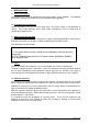
00-19-54 Dual Channel Telephone Interface 1. INTRODUCTION 1.1 Safety Precautions This equipment has been designed and tested to the highest safety standards. The following precautions should be covered to ensure safe operation of the apparatus. 1.2 Transportation and Storage Careful inspection of the unit must be made after it has been subject to transportation or storage. Any serious damage, which could render it dangerous, must be acted upon to safeguard any potential user. 1.
500-19-54 Dual Channel Telephone Interface Page 6 of 19 Issue 1.
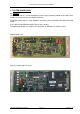
500-19-54 Dual Channel Telephone Interface 2. SYSTEM DESCRIPTION 2.1 Features The telephone unit is a 1U unit containing a power supply and three printed circuit cards; these provide one or two channels of telephone interface. The digital hybrid card has smart algorithms to enhance line cancellation and reduce line howl round. It has software controlled parameters pre-set in the factory. The front panel controls are simple to use and there are indicators to show the status.
500-19-54 Dual Channel Telephone Interface 2.2 General The unit contains one dual hybrid card 500-19-21 which can be used as either a means of converting 2 telephone lines to a line level 4 wire circuit or, if installed with one or two TICs (Telephone Interface Card 500-19-00 for Commander and 700-19-00 for Mercury), allow a full DTMF telephone integration with the Trilogy system.
500-19-54 Dual Channel Telephone Interface Front Panel Controls (single channel) Channel 1 POWER I/F COMMS LINK FAIL HYBRID OK HYBRID OFF OFF ON ON AUTO SEIZE DROP When in Auto mode, an incoming call will be answered with a blip of 2 tones being sent down the line. The tones are an indication to the caller to enter the Direct Dial DTMF tones, if required, to call an individual panel within the Telephone group. This feature is only available when the TIC card is installed.
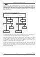
500-19-54 Dual Channel Telephone Interface 2.3 Dual Hybrid Frame – 500/700 -19-54 Card layout ( one or two TIC cards ) PSU LINE 1 DUAL LINE 2 INTERFACE HYBRID INTERFACE Commander Digital Commander 500-19-00 500-19-21 500-19-00 or or Mercury Mercury 700-19-00 700-19-00 FRONT OF FRAME LINE 1 DUAL INTERFACE HYBRID Commander Digital 500-19-00 500-19-21 or PSU Mercury 700-19-00 FRONT OF FRAME Page 10 of 19 Issue 1.
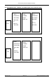
500-19-54 Dual Channel Telephone Interface 3. INSTALLATION 3.1 Dual Hybrid with TIC modules installed 3.2 Dual Hybrid without TIC modules installed 3.3 Specification Trilogy 500-19-5x Telephone Interface Frame Dimensions Mains Input 485mm wide x 44.
500-19-54 Dual Channel Telephone Interface Page 12 of 19 Issue 1.
500-19-54 Dual Channel Telephone Interface 4. CONNECTORS Rear view 4.1 Mains connector - Power connection. IEC mains Pin Number L N E Signal Live Neutral Earth Direction From Unit Input Input Input 4.
500-19-54 Dual Channel Telephone Interface 4.5 Phone connector. RJ11 connector. Pin Number 1. 2. 3. 4. 5. 6. Signal Direction From Unit Line + Line - Input / Output Input / Output NOTE The Trilogy Dual Hybrid frame should only be connected to a Line via an appropriate approved fuse disconnection barrier. Page 14 of 19 Issue 1.
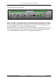
500-19-54 Dual Channel Telephone Interface 5. FRONT PANEL CONTROLS AND INDICATORS Channel 1 POWER I/F COMMS LINK FAIL HYBRID HYBRID OFF OK OFF ON ON AUTO SEIZE DROP 5.1 I/F Power LED Indicates the TIC card is present and powered. 5.2 Hybrid Power LED Indicates the Hybrid card is present and powered. 5.3 Comms Link Fail/OK LED Indicates the state of the data comms between the TIC card and the matrix. 5.4 Hybrid ON/OFF LED Indicates when the Hybrid is ON or OFF hook. 5.
500-19-54 Dual Channel Telephone Interface Page 16 of 19 Issue 1.
500-19-54 Dual Channel Telephone Interface 6. 500-19-21 DUAL HYBRID SET-UP 6.1 Introduction The 500-19-21 card carries two identical circuits and is controlled by the 700/500-19-00 interface cards and/or the front panel controls (see the previous section for information on the controls). Jumpers on the card allow matching to different line and exchange conditions as shown below. For details on the positions of the jumpers, please refer to the circuit board legend. 6.2 6.4 6.2 6.5 6.3 6.3 6.
500-19-54 Dual Channel Telephone Interface Page 18 of 19 Issue 1.
500-19-54 Dual Channel Telephone Interface 7. 500-19-00 TELEPHONE INTERFACE CARD SET-UP 7.1 Introduction The 700-19-00 interface card acts as a buffer between the hybrid that connects directly to the telephone line and the audio and data circuits of the Commander matrix. Each card interfaces one telephone line to one matrix port. The card is largely digital, but there are three level controls that although factory pre-set, can be varied if necessary 7.