
Instructions / Assembly

ASSEMBLY INSTRUCTIONS
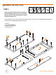
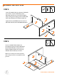
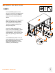
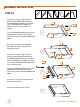
STEP 2
Insert (2) DOWELS (HH) into center of BACK FRAME (F).
Connect DIVIDER (E) with BACK FRAME (F) via DOWELS
(HH) and CONNECTOR SCREW (FF) as shown, making
sure to align groove on DIVIDER (E) with groove on BACK
FRAME (F). Note groove on BACK FRAME (F) should face
DIVIDER (E).
Insert (1) CAM LOCK (GG) into DIVIDER (E) as shown
with arrow on CAM LOCK (GG) pointing
toward BACK FRAME (F). Use
SCREWDRIVER (MM) to turn
CAM LOCK (GG) clockwise
until DIVIDER (E) is pulled
tight with BACK FRAME (F).
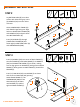
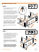
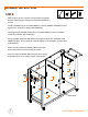
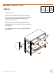
STEP 3
© 2020 TRINITY - 800.985.5506
4
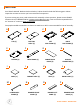
EE (6) HH (4)M (2)B (1) MM (1)
Lay BOTTOM SHELF (B) on a clean
surface with holes facing up. Insert
(4) DOWELS (HH) into inner holes
as shown.
Orient LOWER SHELF FRAME (M)
with TRINITY logo facing out. Align
holes on LOWER SHELF FRAME (M)
with DOWELS (HH) and push down
onto BOTTOM SHELF (B).
Insert (6) SCREWS (EE) through
LOWER SHELF FRAME (M) and
fasten tightly to BOTTOM SHELF (B)
with SCREWDRIVER (MM).
B
MM
M
HH
EE
GG (1) HH (2)
E (1)
MM (1)
MM
HH
E
GG
F
FF
F (1)