,® O I I Owner's Manual / Manual del Propietario Portable IMPORTANT: IMPORTANTE: LEYO Generator / Generador Model / Modelo 01925 READ SAFETY LA SEGURIDAD RULES AND LAS ORDENESY Port_til INSTRUCTIONS CAREFULLY LAS INSTRUCCIONES DETENIDAMENTE Questions? Preguntas? Helpline - 1-888-611-6708 M*F 8-5 CT Troy-Bilt_ isa registeredtrademarkof MTD and isusedunder licenseto Briggs& StrattonPower Products.
Safety Rules 1 TABLE OF CONTENTS Safety Rules.................................... Know Your Generator ............................. SAFETY 2-4 5 Assembly ...................................... Operation .................................... Maintenance ................................. 6-7 8-13 14-15 Storage ........................................ Troubleshooting ................................. Schematic/Wiring Diagram ..................... Replacement Parts ............................ Notes .....
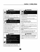
Section 1: Safety Rules DANGER Operate generator ONLY outdoors. WARNING WHEN ADDING FUEL Keep at least 2 feet of clearance on all sides of generator for adequate ventilation. Turn generator DO NOT operate generator insideany buildingor enclosure, includingthe generator compartment of a recreationalvehicle(RV). Fill fuel tank outdoors. DO NOT DANGER overfill tank.Allow space for fuel expansion. Keep fuel away from sparks, open flames, pilot lights, heat, and other ignition sources.
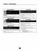
Section 1: Safety Rules WARNING CAUTION See"Don't Overload Generator" on page 13. Start generator and let engine stabilize before connecting electrical loads. ;ENERATOR Disconnect the spark plug wire from the spark plug and place the wire where it cannot contact spark plug. , WARNING Connect electrical loads in OFF position, then turn ON for operation. Turn electrical loads OFF and disconnect from generator before stopping generator. CAUTION DO NOT touch hot surfaces.
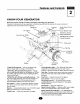
Features and Controls 2 KNOWYOUR GENERATOR Read this owner's manual and safety rules before operating your generator. Compare this illustrationwith your generator to familiarize yourself with the locationsof various controls and adjustments. Savethis manualfor future reference.
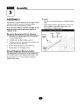
ASSEMBLY To install: Your generator requires attachment of the negative battery cable and is ready for useafter it has been properly serviced with the recommended oil and fuel. If you have any problems with the assembly of your generator, please call the generator helpline at 1-888-61 1-6708. Remove Generator From Carton I. Set carton on a rigid fiat surface with "This Side Up" arrows pointing upward. 2. Carefully open top flaps of shipping carton. 3.
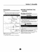
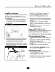
Section 3: Assembly Attach Handle You will need two I/2" or 13 mm wrenches to attach the handle. I. Attach handle to right side of generator frame (viewing unit from front), as shown in Figure 2, with a 60 mm capscrew,flat washers, nylon washers, and lock nut. BEFORE STARTING ENGINE Add Engine • Place generator THE Oil and Fuel on a level surface. CAUTION • Refer to engine manualfor oil and fuel fill information.
Operation USING System THE GENERATOR OPERATING THE G EN ERATO R Ground CAUTION The generator has a system ground that connects the generator frame components to the ground terminals on the AC output receptacles.The system ground is connected to the AC neutral wire (see "Equipment Description", earlier in this manual). See"Don't Overload Generator" on page 13. Special Requirements Start generator and let engine stabilize before connecting electrical loads.
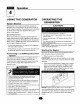
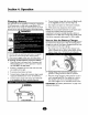
Section 4: Operation Jump Start Procedure If the generator's starting battery fails, usethe following instructions to jump start your generator.You can jump start the generator using any 12Volt automotive or utility style storage battery. I. Unscrew the fuse holder and remove the generator's l0 Amp in-linefuse (Figure 4).Verify the fuse is good or replace with a known good fuse. Reinstall fuse in the fuse holder. 4.
Section 4: Operation Charging a Battery Your generator hasthe capability of recharging a discharged 12Volt automotive or utility style storage battery. DO NOT use the unit to charge any 6Vott batteries. DO NOT use the unit to crank an engine havinga discharged battery. DANGER 6. Connect battery charge cable clamp with black handle to the negative (-) battery terminal (Figure 6). 7. Start engine. Let engine run while battery recharges. 8.
Section 4: Operation COLD WEATH OPERATION ER G EN ERATO R ADAPTER CORD SET Under certain weather conditions (temperatures below 40°F [4°C] and a high clew point), your generator may experience icing of the carburetor and/or the crankcase breather system. The generator is equipped with a 25' generator adapter cord set designedfor a 240Volt, 30 Amp grounded neutral circuit (Figure9).
Section 4: Operation RECEPTACLES Use each receptacle to operate 120Volt AC, single-phase, 60 Hz electrical loadsrequiring up to 2,400 watts (2.4 kW) at 20Amps of current. Use cord sets that are rated for 125Volt AC loads at 20 Amps (or greater). CAUTION 120/240 Volt AC, 30 Amp, NEVER attempt to power a device requiring more amperage than generator or receptacle can supply. Receptacle DO NOT overload the generator. See "Don't Overload Generator".
Section 4: Operation DON'T OVERLOAD G EN ERATO R You must make sure your generator cansupply enough rated (running) and surge (starting) watts for the items you will power at the same time. Follow these simple steps: I. Select the itemsyou wilt power at the same time. 3. Total the rated (running) watts of these items.Thisis the amount of power your generator must produce to keep your items running. See Figure 13. Estimate how many surge (starting) watts you wilt need.
Maintenance 5 GENERAL MAINTENANCE RECOMMENDATIONS 4. After oil hasdrained, reinstall the oil drain plug. 5. Remove the oil drain tray from under the oil drain plug and clean up any spilled oil. The Owner/Operator is responsible for making sure that all periodic maintenance tasks are completed on a timely basis;that all discrepancies are corrected; and that the unit is kept clean and properly stored. NEVER operate a damaged or defective generator. Changing Oil Filter I.
Section 5: Maintenance Generator Maintenance Data Tag Generator maintenance consists of keeping the unit clean and dry. Operate and store the unit in a clean dry environment where it witt not be exposed to excessive dust, dirt, moisture or any corrosive vapors. Cooling air slots in the generator must not become clogged with snow, leaves or any other foreign material. NOTE: DO NOT usea garden hose to clean generator. Water can enter engine fuel system and cause problems.
STO RAG E Engine The generator should be started at least once every seven claysand allowed to run at least 30 minutes. If this cannot be done and you must store the unit for more than 30 days,use the following guidelines to prepare it for storage. Generator Storage • Clean the generator as outlined in "Generator Cleaning". • Check that cooling air slots and openings on generator are open and unobstructed. See engine Other Storage owner's manual for instructions.
Troubleshooting 7 TROUBLESHOOTING Problem Cause Correction I. I. Reset circuit breaker. 2. Contact Authorized service One of the circuit breakers is open. No AC output is available, but generator is running. 2. Fault in generator. 3. Poor connection cord set. 4. Connected I. Short circuit 2. 3. facility. or defective device is bad. 3. Check and repair. 4. Connect another device that is in good condition. Generator runs good at no-load but "bogs" down" when loads are connected. I.
Wiring Diagram and Schematic 8 SCHEMATIC > 1 AUTI ] RESET . IWITCH 10 ANP ,.
Section 8: Wiring Diagram and Schematic WIRING DIAGRAM PB_ NEB BATTERY SPARK PLUG CARB FUEL SHUT BFF is J 13B 13C I
Exploded Views and Parts Lists 9 EXPLODEDVIEW- MAIN UNIT 58 66 17 900 / 68 82 49 D -48 47 22 / 21 20 17 / \ 16 14-- 13 72 \ 7O ,/ 10 0 11 / 12 55
Section 9: Exploded Views and Parts Lists PARTS LIST - MAIN Item I 2 3 4 5 6 7 B 9 10 II 12 13 14 15 16 17 18 19 20 21 22 23 24 25 26 27 28 29 30 31 32 33 34 35 36 37 38 39 40 41 42 43 Part # PI91821GS P|93086GS 192368GS 193263GS |86173GS 31669GS 26911GS 8207 IGS 192470GS 84966G5 22247GS 191265GS 191267GGS !92553GSGS 193320GS 193463GS 185939LG5 192940GS 189302EGS 191815GS 22769GS 36701GS 191190GS 74908GS 191029GS 187365HGS 75246GS NSP 191793GS 193249GS 96796GS 193264GS 191991GS 191990GS 191989GS 191826GS
Section 9: Exploded Views and Parts Lists AC CONTROL PANEL EXPLODED VIEW & PARTS LIST 16 \ 6 7 7 \ \ \ \ \ \ 15 \ \ \ \ \\ 5 17 \ \ \ \\ 14 1 10 5 2 \\\\\ 1 \\\\ 18 Item I 2 3 4 5 6 7 8 9 10 II 12 13 14 15 16 17 18 Part # 188914GS 192273BGS 189167GS 189182GS 189166GS 68759GS 189165GS 84198GS 75207GS 43437GS 189164GS 84543CGS 93857GS 192274GS 82308GS 22694GS 192241GS 192785GS Description COVER, Lid, Controt Panel CONTROL PANEL,Compact CLIP,Hinge Pin Retainer SPRING, Hinge, Pin PIN
Section 9: Exploded Views and Parts Lists DC CONTROL PANEL EXPLODED VIEW 8 // / / / / Item Part # I 192367GS 2 191015GS 3 191016GS 4 192466GS 5 186133GS 6 90418GS 7 192945GS 8 87962GS 9 189520GS Description PANEL, DC Control SWITCH, SRS KNOB, SRSSwitch ASSY,Jack,Coaxial CAR Battery Charge OUTLET, 12VDC, Snap PLATE,Switch Key BREAKER,Circuit SCREW m & PARTS LIST
Section 9: Exploded Views and Parts Lists ALTERNATOR EXPLODED VIEW & PARTS LIST \ '1 \ 2 7 \ 9 11 10 Item I 2 3 4 5 6 7 8 9 10 II 12 13 14 15 Part # 186059GS 192171GS 192186AGS 186060GS 86308KGS 66386GS 66849GS 22694GS 81917GS 19105lAGS 66849CGS 23762GS 65795GS 191653GS 193074GS Description ADAPTER, Mounting, Alternator ROTOR STATOR RBC, (with O-Ring p/n 189197GS) SCREW ASSY,Holder, Brush SCREW RECEPTACLE,6 pin PIN, Roll ASSY,Wire, Ground SCREW WASHER RECTIFIER BOARD, Circuit, System Control H
Notes NOTES
Reglas de Seguridad 1 TABLA DE CONTENIDOS REGLAS ReglasDe Seguridad ................................ Conozca Su Generador ................................ Ensamblaje........................................ Funcionamiento .................................... Mantenimiento ..................................... AImacenamiento ...................................... 26-28 29 30-3 I 32-38 39-40 4I Diagnosticos De Averfas ................................ Esquem_tico / Digrama El_ctrico ......................
Secci6n 1: Reglas de Seguridad PELIGRO ADVERTENCIA Opere el generador SOLAMENTE al aire libre. CUANDO Mantenga al menos 2 pies de espado libre alrededor del generador, para la adecuada ventilaci6n. NO opere el generador dentro de un edificio o lugar cerrado, incluyendo el compartimiento del generador en un vehiculo recreativo o R_L AI_IADA COMBUSTIBLE Apague el generador (posici6n OFF) y d_jelo enfriar al menos por 2 minutos antes de remover la tapa de la gasolina.
Secci6n 1: Instrucciones de Seguridad PRECAUCION ADVERTENCIA Vea "No sobrecargue generador" en la p_gina 38. Encienda su generador y deje clue el motor se estabilice antes de conectar las cargas el/actricas. ;ENERADOR Conecte las cargas el_ctricas en la posici6n de apagado (OFF), luego encienda (ON) para su operaci6n. Siempre desconecte el alambre de la bujla y col6quelo donde no pueda entrar en contacto con la bujla.
Caracteristicas ¥ Mandos 2 CONOZCA LEA ESTE Compare SU GENERADOR MANUAL DEL PROPIETARIOY las ilustraciones con su Generador manual para referencias LAS REGLAS para familiarizarse DE SEGURIDAD con las ubicaciones ANTES DE OPERAR de los diferentes controles SU GENERADOR. y ajustes. Conserve este futuras.
MONTAJE Para instalar: Su generador requiere de ciertos procedimientos de montaie y solo estar_ listo para ser utilizado despu_s de haberle suministrado servicio con el combustible y aceite recomendados. I. Si usted tiene problemas con el montaje de su generador, pot favor Ilame a la linea de ayuda para generadores al 1-888-61 1-6708. Para Retirar El Generador De La Caja Tornillo I. Coloque la caia sobre una superficie plana y rigida, con las flechasque dicen "this side up" hacia arriba. 2.
Secci6n 3: Montaje ANTES DE DARLE MOTOR Fije el Asa Necesitar6 I. dos Ilaves inglesas de 13 mm o I/2" para fiiar el asa. Fije el asa al lateral derecho del bastidor del generador ARRANQUE AL (visto desde la parte delantera de la unidad), como se muestra en la Figura 18. Para ello utilice un 60 mm tornillo, arandelas, arandelas de nylon y una tuerca. Agregar Aceite Coloque al Motor y Combustible la generador sobre una superficie nivelada.
Operaci6n USO DEL GENERADOR Tierra del Sistema OPERANDO EL GENERADOR PRECAUCION El generador dispone de una conexi6n a tierra del sistema que conecta los componentes del bastidor a los terminales de tierra de los enchufes hembra de salida de CA. La tierra del sistema est_ conectada al cable de CA neutro conectado al bastidor del generador Vea "No sobrecargue generador" en la p_gina 38.
Secci6n 4: Operaci6n Procedimiento de Arranclue en Puente Si fa[la la bateria de arranque del generador, siga estas instruccionespara arrancarlo en puente. Puede arrancar el generador utilizando una bateria secundaria o de automocibn de 12 voltios. I. Desatornille el portafusibles y retire el fusible en linea de 10 A del generador (Figura 20). Compruebe el estado del fusible y,si es necesario, sustit_yalo.Vuelva a colocar el fusible en el portafusibles. 4.
Secci6n 4: Operaci6n Carga de la Bateria Su generador tiene la capacidad de recargar baterlas descargadas de acumuladores tipo servicio o automotriz de 12Voltios. NO utilice la unidad para cargar baterias de 6Voltios. NO use la unidad para mover motores que tengan la baterla descargada. PELIGRO 6. Conecte el sujetador del cable de carga de la bateria que tiene la manija negra al terminal negativo (-) de la bateria (Figura 22). 7. Arranque el motor.
Secci6n 4: Operaci6n OPERACI( N DURANTE CLIMA FRiO UN Baio ciertas concliciones ambientales (temperaturas pot debajo de los 40-_F[4-_C]y un punto alto Dew), su generador puede experimentar congelamiento del carburador y/o el sistema de respiradero clel cigLiehal. 2. Aseg_rese que existe un espacio mfnimo de dos pies entre el laclo abierto de la caja y el obieto m_s cercano. 3. Coloque la parte abierta fuera clel viento y otros elementos. 4.
Secci6n 4: Operaci6n RECEPTACULOS JUEGO DE CABLES DEL ADAPTADOR DEL GENERADOR El generador est_ equipado con un Juego de Cables del Adaptador del Generador de 25 pies,disefiado para un circuito neutro a tierra de 240 voltios, 30 Amperios (Figura 25). El juego de cables del adaptador del generador provee un suministro conveniente de energia para cualquier emergencia en su propiedad, de tal manera que su generador pueda ser operado seguramente en el exterior.
Secci6n 4: Operaci6n 120 Volt AC, 20 Amp, Recept_culos 120/240 Dobles Voltios AC, 30 Amp, Receptgculo de Seguridad Cada recep_culo (Figura 27) est,i protegido en contra de sobrecargas por un corto-circuitos de, del tipo "empuje para reposicionar". Use un tap6n NEMA LI4-30 con este recept,iculo. Conecte un juego de cable de 4 alambres, clasificado como 250 Voltios AC a 30Amps (o mayor) (Figura 28). Usted puede usar el mismo cable de 4-alambres si planea trabaiar con una carga de 120Voltios.
Secci6n 4: Operaci6n NO SOBRECARGUE GENERADOR EL 4. Conecte y encienda la pr6xima carga. 5. De nuevo, permita que el generador se estabilice. 6. Capacidad Usted debe asegurarse que su generador puede proveer el suficiente vataje calificado (cuando est_ funcionando) y de carga (al encender) para los aparatos a los cuales va a proveer la energia, al mismo tiempo. Siga estos pasos: I. Seleccione los aparatos que recibir_n la energia, al mismo tiempo. 2.
Mantenimiento 5 RECOMENDACIONES GENERALES DE 4. Una vez vaciado el aceite, vuelva a colocar vaciado de aceite. S. Retire la bandeja de vaciado de aceite de debaio del tap6n y limpie los restos de aceite. MANTENIMIENTO El propietario I operador es responsable por asegurarse de que todos los trabaios peri6dicos de mantenimiento se lleven a cabo adecuadamente; que todos los problemas son resueltos; y que la unidad se mantiene limpia y adecuadamente almacenada.
Secci6n 5: Mantenimiento Mantenimiento del Generador Placa de Caracterlsticas El mantenimiento del generador consiste en conservar la unidad limpia y seca.Opere y almacene la unidad en un ambiente limpio y seco donde no ser_ expuesta a[ polvo, suciedad,humedad o vapores corrosives. Las ranuras del aire de enfriamiento del generador no deben estar tapadas con nieve,hojas, o cualquier otro material extrahos.
Almacenamiento 6 ALMACENAMIENTO Almacenando El generador deber_ ser encendido al menos una vez cada siete dfas y deber_ dejarlo funcionar al menos durante 30 minutos. Si no puede hacer esto y debe almacenar la unidad por mgs de 30 dfas,siga las siguientes instruccionespara preparar su unidad para almacenamiento. Consulte el manual del propietario del motor para las instruccionesde cbmo preparar adecuadamente el motor para su almacenamiento.
Diagnosticos de Averias 7 DIAGNOSlTICOS Problemo El motor existe DE AVERiAS Causa est& funcionando I. El interruptor est_ abierto. I. Reposicione 2. Conexi6n mal o defectuosa del iuego de cables. 2. Revise y repare. 3. El dispositivo 3. Conecte otro dispositivo que est_ buenascondiciones. 4. Averia en el generador. 4. Contacte el distribuidor de servicio autorizado. Corto circuito conectadss. I. pero no salida de AC disponsible. I.
POLJTICA "Troy-BiltO es una marca registrada PARA EL PROPIETARIO DE EQUIPOSTROY-BILT® Efectiva desde el Iro de Enero, 2003 GARANTIA LIMITADA de MTD bajo licencia de Briggs & Stratton Power Products. Briggs & Stratton Power Products reparar_ o sustituir_ sin cargo alguno cualquier componente del equipo** que presente defectos de materiales y/o mano de obra. Los gastos de transporte de las piezas enviadas para reparar o sustituir conforme a los t_rminos de esta garantta corrergn a cargo del comprador.
TROY-BILT® OWNER WARRANTY POLICY Effective January I, 2003 LIMITED WARRANTY "Troy-Bitt® is a registered trademark of MTD and is used under license to Briggs & Stratton Power Products. Briggs & Stratton Power Products will repair or replace, free of charge, any part, or parts of the equipment** that are defective in material or workmanship or both.Transportation charges on parts submitted for repair or replacement under this warranty must be borne by purchaser.