
User manual

• Please handle the product carefully. Jolts, impacts or a fall even from a low height
can damage the product.
• Also observe the safety and operating instructions of any other devices which are
connected to the product.
• Make sure that the assembly group is put into operation correctly. Please follow
the operating instructions carefully in doing so.
• The assembly group must not be installed in/on easily ammable materials.
• In commercial and industrial facilities the regulations for the prevention of accidents
as laid down by the professional trade association for electrical equipment and
devices must be observed.
• In schools and training centres as well as in hobby and DIY workshops, the use
of assembly groups must be supervised by adequately trained personnel in a
responsible manner.
• Never pour out any liquids above the assembly group. There is the risk of the
assembly group being damaged.
• Consult an expert when in doubt about operation, safety or connection of the
device.
• Maintenance, modications and repairs are to be performed exclusively by an
expert or at a qualied shop.
• If you have questions which remain unanswered by these operating instructions,
contact our technical support service or other technical personnel.
Assembly
• The suitable relay must be soldered in to the relay circuit board “without relay” before initial
operation. The following tools and accessories are required for soldering:
- a soldering iron with a wet cleaning sponge
- electronics tin-solder
- small at-nosed pliers as well as
- an electronic wire-cutter
- a heat-resistant rubber pad is recommended as base on which to work
• The assembly is only to be performed on the top side of the circuit board (with insertion
legend print). Soldering is performed on the underside.
• Make sure that the connection wires of the relay are bent off by 45° after insertion to the
circuit board. This prevents the relay from falling off when the circuit board is turned around.
• Switch on your soldering iron or soldering station and heat up to about 320 to 400 °C (in
accordance with the tin-solder being used, lead/lead-free).
• Make sure that the soldering iron is placed safely! Burn and re hazards!
Soldering
Be cautious while soldering. The soldering iron and tip get very hot and may cause
severe skin burns.
Soldering irons are not suitable for children.
Do not leave warm or hot soldering irons unattended. Fire hazard!
• After assembly of the circuit board the connections should be soldered.
• Make sure you always have a clean soldering tip during the soldering process. Clean the tip
with a wet cleaning sponge prior to each soldering.
• The soldering process should only be performed as long as necessary and in as short a time
as possible. Heat up the soldering joint and the connection lead with the soldering tip and add
some tin-solder immediately.
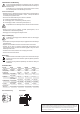
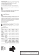
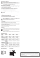
• Wait until the solder has blended neatly and then
remove the soldering tip. The soldering joint should
be cone-shaped and shiny. See illustration.
• Remove the protruding connecting leads above the soldering joint by using Electronics wire-
cutter pliers. Make sure that no wire ends y off; risk of injury!
• Recheck the soldering joints for cleanliness and make sure there are no short-circuits that
have been created accidentally.
Putting into operation and use
To ensure proper set-up and operation, please read the operating instructions and
safety instructions carefully before using the device.
You may only connect the assembly group when the voltage is off. Make sure that
all circuit board components and connection leads do not carry any power.
Connecting the relay circuit board
• The operating voltage (= relay inductor voltage) of the circuit board is provided by the strip
terminal with label “IN”. Please observe the correct polarity. + = positive pole - = negative
pole. The circuit board may only be operated in DC voltage.
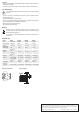
• The connection of the switching contacts is performed through the terminals “CO/NC/NO”
CO = Common switching contact (contact 6 and 7).
NC = relay switching output “Normally Closed Contact”. Closed when non-operative (contact 1).
NO = relay switching output “Normally Open Contact”. Open when non-operative (contact 12).
For information on the switching capacity please refer to the technical specications.
Operating instructions
Relay circuit board REL-PCB 4
Item no. 503322 without relay
Item no. 1570052 with relay 5 V/DC
Item no. 1566300 with relay 12 V/DC
Item no. 1566301 with relay 24 V/DC
Intended use
The relay circuit boards are used for the assembly of print relays with inductor voltages of
4 - 30 V/DC. The circuit board model “without relay” is used as a universal component for the
assembly of a set of printed circuit board relays with corresponding print image (a list of the
suitable relays that are currently in the product line of Conrad Electronic, can be found under
the respective relay circuit board under www.conrad.com). The model “with relay” has already
been assembled with a relay for the corresponding nominal operating voltage. A connection
can be performed easily by using screw contacts on the circuit board. The max. switching
capacity must not exceed the capacity indicated in the technical specications.
The assembly group must be installed completely in a casing where it is protected from
accidental contact.
Assembly and commissioning may only be carried out by a specialist who is familiar with the
relevant regulations and the ensuing risks.
An installation on DIN rails is also possible by using optional supplementary components.
If several relay circuit boards are assembled on a sub-module carrier board, separation straps
(item no. 503340) must be used due to lack of space and in order to comply with the Electronics
Safety Regulations.
For safety and approval purposes, you must not rebuild and/or modify this product. If you use
the product for purposes other than those described above, the product may be damaged.
In addition, improper use can cause hazards such as short circuiting, re, electric shock etc.
Read the instructions carefully and keep them. Make this product available to third parties only
together with its operating instructions.
This product complies with the statutory national and European requirements. All company
names and product names are trademarks of their respective owners. All rights reserved.
Delivery content
• Relay circuit board
• Operating instructions
Latest operating instructions
Download the latest operating instructions via the link www.conrad.com/downloads or scan the
QR code shown. Follow the instructions on the website.
Explanation of symbols
The lightning symbol inside a triangle is used when there is a potential risk of
personal injury, such as electric shock.
An exclamation mark in a triangle indicates important instructions in this operating
manual that absolutely have to be observed.
The arrow symbol indicates specic tips and advice on operation.
Safety instructions
Read the operating instructions carefully and especially observe the safety
information. If you do not follow the safety instructions and information
on proper handling in this manual, we assume no liability for any resulting
personal injury or damage to property. Such cases will invalidate the warranty/
guarantee.
• The device is not a toy. Keep it out of the reach of children and pets.
• Do not leave packaging material lying around carelessly. This may become
dangerous playing material for children.
• Protect the product from extreme temperatures, direct sunlight, strong jolts, high
humidity, moisture, ammable gases, vapours and solvents.
• Do not place the product under any mechanical stress.
• If it is no longer possible to operate the product safely, take it out of operation and
protect it from any accidental use. Safe operation can no longer be guaranteed
if the product:
- is visibly damaged,
- is no longer working properly,
- has been stored for extended periods in poor ambient conditions or
- has been subjected to any serious transport-related stresses.