TRUE RESIDENTIAL ® 15 INCH AND 24 INCH UNDERCOUNTER I N S TA L L G U I D E A N D U S E R ' S M A N U A L “B” RE VISIONS PRESERVE THE MOMENT®
THANK YOU FOR YOUR PURCHA SE
TABLE OF CONTENT S INSTAL L ATION CHECK LIST 2 OWNERSHIP 4 S AFE T Y PRECAUTIONS 4 DISP O S AL OF OL D REFRIGER ATOR 4 CFC DISP O S AL 4 UNCR ATING 5 EL ECTRICAL SPECIFICATIONS 6 OUTD O OR USE 6 INSTAL L ATION SPECIFICATIONS FOR STAINL ES S S OLID AND GL A S S D O OR 7-12 INSTAL L ATION SPECIFICATIONS FOR S OLID PANEL RE ADY (OP), GL A S S FR AMED PANEL RE ADY (O G) AND INTEGR ATED PANEL 13 -2 9 INSTAL L ATION SPECIFICATIONS FOR BE V ER AGE DISPENSER UNITS 3 0 - 3 8 INSTAL LING TOE K ICK 3 8 L E V ELING
INS TALL ATION CHECKLIS T To ensure a proper installation, this checklist should be completed to ensure that no part of the process has been overlooked.
3-6 Ownership Safety Precautions Disposal of the O ld Refrig er ator CFC D i s p o s a l Uncr ating Elec tric al S pecific ations O u t doo r U s e Ins tall ation S pecific ations PRESERVE THE MOMENT® 15 INCH & 24 INCH INSTALL GUIDE 3
OWNERSHIP To insure that your unit works properly from the first day, it must be installed properly. (We highly recommend a trained refrigeration mechanic and electrician install your True Residential ® Cabinet.) The cost of a professional installation is money well spent. Before you start to install your True Residential ® Cabinet, carefully inspect it for freight damage. If damage is discovered, immediately file a claim with the delivery freight carrier.
UNCR ATING INSPECT FOR CONCEALED DAMAGE. AGAIN, IMMEDIATELY FILE A CLAIM WITH THE FREIGHT CARRIER IF THERE IS DAMAGE. Required Tools: • Cutting utensil (utility knife) • Hammer • Crowbar • Phillips head screwdriver B. IMPORTANT: Cut green polyband and remove styrofoam block before removing refrigerator from pallet. The following procedure is recommended for uncrating the unit: C. Remove skid by carefully lifting the refrigerator off and place skid aside.
ELEC TRIC AL SPECIFIC ATIONS The unit should always be plugged into its own individual electrical circuit, which has a voltage rating that matches the rating plate. This provides the best performance and also prevents overloading house wiring circuits which could cause a fire hazard from overheated wires. Never unplug your refrigerator by pulling on the power cord. Always grip plug firmly and pull straight out from the outlet.
7 - 12 Ins tall ation S pecific ations f o r S t a i n l e s s S o l i d ( SS ) a n d G l a s s D oo r ( SG ) PRESERVE THE MOMENT® 15 INCH & 24 INCH INSTALL GUIDE 7
INS TALL ATION SPECIFIC ATIONS - S TAINLESS SOLID & G L A SS DOOR True’s Stainless Solid and Glass Door units are designed to be inserted into a cabinet opening or free standing. Below are recommended dimensions for rough opening. TRUE’S CABINETS ARE UL RATED FOR USE IN OUTDOOR SETTINGS. IN OUTDOOR LOCATIONS WHERE THE AMBIENT TEMPERATURE REGULARLY EXCEEDS 95˚F, IT IS RECOMMENDED TO VENT THE REAR OF THE CUT OUT OPENING IN THE AREA SHOWN BELOW FOR OPTIMUM PERFORMANCE. THE RECOMMENDED CUT OUT SIZE IS 4" X 10".
24 INCH ALL REFRIGERATOR TUR-24-R/L-SS-B TUR-24-R/L-SG-B FREEZER TUR-24D-SS-B TUF-24-R/L-SS-B TUF-24D-SS-B BEVERAGE CENTER WINE CABINET DUAL ZONE WINE CABINET TBC-24-R/L-SG-B TWC-24-R/L-SG-B TWC-24DZ-R/L-SG-B 25 3/4" 23 7/8" 23 7/8" 46 7/8" 34 1/4" 34 1/4" 25 1/4" 4 1/8" 3 3/4" D IM EN SI O N S M AY VA RY BY ± 1 / 8 " 15 INCH & 24 INCH INSTALL GUIDE 9
B e verage dispenser TUR-24BD-R/L-SS-B TUR-24DD-R/L-SS-B 24" SING L E TA P UNI T A C C OMMO D AT E S (1) SHO R T 1/ 4 B A R R EL , (1) SL IM 1/ 4 B A R R EL , O R (1) 1/ 6 B A R R EL . 24" DUA L TA P UNI T A C C OMMO D AT E S (2) 1/ 6 B A R R EL S O R (1) SL IM 1/ 4 B A R R EL A ND (1) 1/ 6 B A R R EL .
1 5 INCH ALL REFRIGERATOR TUR-15-R/L-SS-B WINE CABINET TUR-15-R/L-SG-B TWC-15-R/L-SG-B 25 3/4" 23 7/8" 14 7/8" 37 7/8" 34 1/4" 34 1/4" 16 1/4" 4 1/8" 3 3/4" D IM EN SI O N S M AY VA RY BY ± 1 / 8 " 15 INCH & 24 INCH INSTALL GUIDE 11
BEVERAGE DISPENSER TUR-15BD-R/L-SS-B 15 " SING L E TA P UNI T A C C OMMO D AT E S (1) SL IM 1/ 4 B A R R EL O R (1) 1/ 6 B A R R EL .
13 - 27 Ins tall ation S pecific ations fo r S o l i d Pa n el R e a dy (o p) a n d G l a s s Fr a m ed Pa n el R e a dy (o g) PRESERVE THE MOMENT® 15 INCH & 24 INCH INSTALL GUIDE 13
24 INCH INS TALL ATION SPECIFIC ATIONS SOLID (OP) AND G L A SS FR A MED PANEL (OG) True’s 24 inch units with Solid and Glass Framed Panels are designed to be inserted into a cabinet opening or free standing. Below are recommended dimensions for rough opening. TRUE’S CABINETS ARE UL RATED FOR USE IN OUTDOOR SETTINGS. IN OUTDOOR LOCATIONS WHERE THE AMBIENT TEMPERATURE REGULARLY EXCEEDS 95˚F, IT IS RECOMMENDED TO VENT THE REAR OF THE CUT OUT OPENING IN THE AREA SHOWN BELOW FOR OPTIMUM PERFORMANCE.
24 INCH ALL REFRIGERATOR TUR-24-R/L-OP-B TUR-24-R/L-OG-B BEVERAGE CENTER TBC-24-R/L-OP-B TBC-24-R/L-OG-B FREEZER TUR-24D-OP-B TUF-24-R/L-OP-B TUF-24D-OP-B WINE CABINET TWC-24-R/L-OP-B TWC-24-R/L-OG-B BEVERAGE DISPENSER DUAL ZONE WINE CABINET TWC-24DZ-R/L-OP-B TWC-24DZ-R/L-OG-B TUR-24BD-R/L-OP-B TUR-24DD-R/L-OP-B 15 INCH & 24 INCH INSTALL GUIDE 15
23 7/8" 3/4" 23 7/8" 23 1/8" 46 7/8" 34 1/4" 34 1/4" 25 1/4" 4 1/8" 3 3/4" 23 7/8" 23 7/8" 23 1/8" 42 5/8" 34 1/4" 34 1/4" 21" 4 1/8" 3 3/4" 23 7/8" 23 7/8" 11 7/8" 23 1/8" 10 1/4" 46 7/8" 50" 50" 25 1/4" 34 1/4" 34 1/4" 4 1/8" 3 3/4" 24" SIN G L E TA P UNI T A C C O MM O D AT E S (1) SH O R T 1/ 4 B A R R E L , (1) SL IM 1/ 4 B A R R E L , O R (1) 1/ 6 B A R R E L .
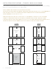
1 5 INCH INS TALL ATION SPECIFIC ATIONS SOLID (OP) AND G L A SS FR A MED PANEL (OG) True’s 15 inch units with Solid and Glass Framed Panels are designed to be inserted into a cabinet opening or free standing. Below are recommended dimensions for rough opening. TRUE’S CABINETS ARE UL RATED FOR USE IN OUTDOOR SETTINGS. IN OUTDOOR LOCATIONS WHERE THE AMBIENT TEMPERATURE REGULARLY EXCEEDS 95˚F, IT IS RECOMMENDED TO VENT THE REAR OF THE CUT OUT OPENING IN THE AREA SHOWN BELOW FOR OPTIMUM PERFORMANCE.
1 5 INCH ALL REFRIGERATOR TUR-15-R/L-OP-B TUR-15-R/L-OG-B WINE CABINET TWC-15-R/L-OP-B TWC-15-R/L-OG-B BEVERAGE DISPENSER TUR-15BD-R/L-OP-B 18 TRUE RESIDENTIAL®
14 7/8" 23 7/8" 37 7/8" 34 1/4" 34 1/4" 16 1/4" 4 1/8" 3 3/4" 23 7/8" 14 7/8" 23 1/8" 7 1/2" 10 1/4" 50" 37 7/8" 50" 34 1/4" 16 1/4" 34 1/4" 4 1/8" 3 3/4" 15 " SING L E TA P UNI T A C C OMMO D AT E S (1) SL IM 1/ 4 B A R R EL O R (1) 1/ 6 B A R R EL .
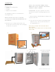
CUS TOM PANEL INS TALL ATION - SOLID DOOR REFRIG ER ATOR / FREEZER Overlay units can be fitted with custom panels to match adjacent cabinetry. Two specification options for panels sizes are given in these instructions for overlay units: Standard overlays and Integrated Panels. The standard overlay panel dimensions fully cover the provided appliance door. The integrated panel options extend above the door and conceal the hinge assembly to match full overlay cabinet doors. See pictures below for reference.
CUS TOM PANEL INS TALL ATION - SOLID DOOR REFRIG ER ATOR / FREEZER S TANDARD OVERL AY PANEL 3/4" 23 5/8" 14 5/8" B A S O L ID D O O R 24 INCH 15 INCH DOOR PANEL WIDTH 235/8 " 145/8 " DOOR PANEL HEIGHT 29 23/32 " 2923/32 " DOOR PANEL DEPTH 3/4" max 3/4" max DOOR PANEL WEIGHT 20 lb. max 20 lb.
CUS TOM PANEL INS TALL ATION - G L A SS DOOR REFRIG ER ATOR S O L ID D O O R 3/4" 23 5/8" S TANDARD OVERL AY PANEL 14 5/8" B A 24 INCH 15 INCH DOOR PANEL WIDTH 235/8 " 145/8 " DOOR PANEL HEIGHT 29 23/32 " 2923/32 " DOOR PANEL DEPTH 3/4" max 3/4" max DOOR PANEL WEIGHT 10 lb. max 10 lb.
CUS TOM PANEL INS TALL ATION - DR AWER REFRIG ER ATOR / FREEZER S TANDARD OVERL AY PANEL DRAWER PANEL WIDTH 235/8 " DRAWER PANEL HEIGHT 1411/16 " DRAWER PANEL DEPTH 3/4" max 235/8 " TOP DRAWER REFRIGERATOR 235/8 " TOP & BOTTOM DRAWER FREEZER 1411/16” 1411/16” SPEC SAME PANEL FOR TOP & BOTTOM FREEZER DRAWERS. FOR BOTTOM DRAWER ROTATE PANEL 180º.
SOLID (OP) AND G L A SS FR A MED PANEL (OG) INS TALL ATION Required Tools: • • • • Phillips Screwdriver 1 3/8" Wrench 1/8" Drill Bit Ten (10) Screws #6 NOTE: THE LENGTH OF OVERLAY PANEL MOUNTING SCREWS NEED TO BE 3/4” PLUS THE THICKNESS OF THE PANEL, MINUS 1/4”. (3/4”+ THICKNESS OF THE OVERLAY PANEL1/4”= LENGTH OF SCREW). TYPES AND LENGTHS OF SCREWS CAN VARY DEPENDING ON THE MATERIAL USED SEE PAGES 21-22 FOR OVERLAY PANEL DIMENSIONS BEFORE INSTALLING.
6. Once all holes are pre drilled use the appropriate specified screws to secure the overlay panel onto the front of the refrigerator door. 7. Reinstall all components in reverse order. Door gasket snaps back into place. Overlay panel and door stay aligned with each other while installing.
DR AWER OVERL AY PANEL INS TALL ATION Required Tools: 1 • Phillips Screwdriver • 1/8" Drill Bit SEE PAGE 21 FOR OVERLAY PANEL DIMENSIONS BEFORE INSTALLING. FOR EASY OVERLAY INSTALLATION, DRAWER FRONT REMOVAL IS REQUIRED. 1. Open the drawer and detach the front drawer panel by removing four #2 Phillips screws (two on each side). (See image 1). Save all these screws for later reinstallation. 2 2. Remove front drawer panel gasket. 3.
6 Back of drawer 7 8 D R AW E R O V E R L AY PA N E L 24 IN CH 15 INCH & 24 INCH INSTALL GUIDE 27
28 - 35 Ins tall ation S pecific ations for Beverage Dispenser Units 28 TRUE RESIDENTIAL® PRESERVE THE MOMENT®
TAPPER UNIT INS TALL ATION UNDER COUNTER TOPS Required Tools: • 2" Diameter PVC pipe (12" long). Will need to be cut down to size when refrigeration unit is installed • Silicone Caulk When installing under counter tops use the dimensions in the diagrams for cutting into the counter top. Silicone caulk around the edge of the PVC pipe after it has been installed. Assemble drip tray and place it on top of unit as shown.
15 IN CH 7 7/16 " 211/16 " 6 3/32 " 815/16 " 10 9/32 " 5/32 " 2 3/8 "O.D. 211/16 " Drip tray 13 5/8 " 12 9/32 " 24 IN CH 11 31/32 " 211/16 " 10 5/8 " 9 3/8 " 10 23/32 " 5/32 " 2 3/8 "O.D.
INS TALLING DR AF T S TANDARD AND HOOK UP Required Tools: • • • • Phillips Head Screwdriver Adjustable Wrench 1 3/8" I.D. plastic tubing (3’) (2) Hose clamps 2 PARTS IN KIT: 1. CO 2 Tank (Shipped empty. Fill before use) 2. Draft Standard 3. Draft Standard Screws 4. Draft Head 5. CO 2 Pressure Regulator (single version/double version) 6. Chill Hose 7. Rubber Washer 8. CO 2 Hose 9. Securing strap 10.
INS TALLING DR AF T S TANDARD AND HOOK UP (CONTINUED) 1. Place rubber washer over draft standard mounting holes. 1 2. Secure the draft standard to the cabinet with the screws provided. 3. Remove the draft cap and run the chill hose to the top of the draft standard. Hook the hose onto the stainless tube to keep hose from falling out (This hose will keep the draft standard cold). 4. Reinstall the draft cap. 2 5. Hook up the pressure regulator to the CO 2 tank.
7. Tighten the clamp down on the beer line hose. 7 8. Connect the CO 2 hose to tapper. NOTE: Make sure clamp is on the hose prior to attaching. 9. Tighten the clamp down on the CO 2 hose. 10. Install the beer tapper onto the keg. The tapper has notches that must line up. Once the notches are lined up, turn the tapper to secure it to the keg.
PRESSURE DISPENSING PRESSURES DIFFER ACCORDING TO: • The type of draft dispensing system • The length of draft dispensing line • The actual product - some require more, some require less • The temperature of the product • The pressurizing agent: air pressure, CO2 or special blended gases HELPFUL HINT S ON M AINTAINING THE CORREC T PRESSURE • Know which pressurizing agent to use on which product and why • Monitor your regulators to ensure applied pressure remains constant • Keep equipment in good repair TAP
CHANG ING CO 2 G A S CYLINDER FOLLOW THESE INSTRUCTIONS AT ALL TIMES WHEN YOU REPLACE A CO2 GAS CYLINDER: 1. Close cylinder at “A”. 2. Remove tap “D” from barrel. Pull pressure release ring on body of tap to release pressure remaining in line. (Do not close “C”). 3. Remove or loosen regulator key “B” by turning counter clockwise. 4. Remove regulator from used cylinder at “E”. 5.
CLE ANING INS TRUC TIONS FOR DR AF T TOWERS BEER TAP CLEANING KIT REQUIRED TOOLS Draught dispensers, regardless of design, must be cleaned on a regular basis. Flushing your draught dispenser with water only is not enough. Cleaning is recommended whenever changing to a fresh keg. NO T E: U SE CL E A NER S A P P R O V ED BY YOUR BEER SUP P L IER A ND F O L L OW T HEIR IN S T RUC T ION S.
36 - 39 I n s t a l l i n g To e K i c k Le veling Refrig er ator I n s t a l l i n g A n t i -T i p B r a c k e t s Ins talling Ins talling the the 1 2 0 ° D oo r S t o p ( S t a n d a r d ) 9 0 ° D oo r S t o p ( O p t i o n a l ) PRESERVE THE MOMENT® 15 INCH & 24 INCH INSTALL GUIDE 37
INS TALLING THE TOE KICK 1. Remove from package that is taped to back of unit 2. Line up and attach the toe kick to the bottom of the cabinet using the magnets. TOE KICK IS ATTACHED TO BACK OF UNIT LE VELING REFRIG ER ATOR 1. Set unit in its final location. Be sure there is adequate ventilation in your room. 2. Proper leveling of your True unit is critical to operating success (for non-mobile models). Effective condensate removal and door operation will be effected by leveling.
TRUE RESIDENTIAL 211354 ® *211354* 3.23.17 AC ANTI-TIP BRACKET INSTALLATION PRODUCT ADVISEMENT KIT INCLUDES TOOLS REQUIRED • 2 Anti-tip brackets • Power drill • 4 Concrete screws (blue) • Measuring Tape • 4 Wood screws (brass) IMPORTANT! ALL FREE STANDING DRAWER (TUR-24D) OR STACKED UNITS MUST HAVE ANTI-TIP BRACKETS INSTALLED. TIP-OVER HAZARD: A CHILD OR ADULT CAN TIP THE REFRIGERATOR. FAILURE TO FOLLOW THESE INSTRUCTIONS CAN RESULT IN PROPERTY OR BODILY HARM.
TRUE RESIDENTIAL 211354 ® *211354* 3.23.17 AC ANTI-TIP BRACKET INSTALLATION PRODUCT ADVISEMENT STEP 2 To mount the anti-tip bracket to wood floor, drill pilot holes for each of the bracket holes. To mount the anti-tip bracket to concrete or ceramic floor use a masonry bit to drill pilot holes. Align anti-tip bracket holes with the holes in the floor. Fasten anti-tip bracket with screws provided using the brass colored screw for wood, or blue colored masonry screw for concrete.
INS TALLING THE 1 20 ° DOOR S TOP All units are provided with an optional door stop. When installed, the door stop will restrict the door from opening past approximately 120º to prevent damage to surrounding cabinets. To install the door stop, use the 2 screws provided and secure the bracket to the bottom of the door on the same side as the hinge.
INS TALLING THE 90 ° DOOR S TOP 1 REQUIRED TOOLS: • • 3/8” Socket wrench Phillips screwdriver KIT: • • 90º Hinge door stop Door stop bracket 1. Remove toe kick. 2 2. WARNING: Support the door while removing hinge. Door is heavy and weight will cause it to drop if not supported. Remove 2 3/8” bolts to detach 120º door hinge (standard). 3. Slowly remove door from unit by sliding down from top hinge. 3 4. Install door stop using screws already installed. Reinstall door by sliding up into top hinge.
40 - 49 Tr u e P r e c i s i o n C o n t r o l® O p e r at i o n and Cabinet Components ( A l l M od e l s ) 24 Inch Refrig er ator & Free zer 24 Inch D ual Zone Wine Cabine t 24 Inch Refrig er ator D r awers 24 Inch Freezer Dr awers 1 5 Inch Refrig er ator Home Al arm System S h elv i n g A d j us tm en t Stacking kit instructions PRESERVE THE MOMENT® 15 INCH & 24 INCH INSTALL GUIDE 43
24 INCH REFRIG ER ATOR & FREEZER (FREE ZER NOT AVAIL AB LE IN G L A SS D O O R) = Power unit off / on cuts power to all relays = To display set point = = Press to change set point down Press to change set point up = To turn on accent light - This will leave light on all the time even when the door is closed = To switch color LED’s - 14 color TruLumina ® patent.
TRUE ALL REFRIGERATOR / FREEZER COMPONENTS TUR / TUF LOCATION OF SERIAL TAG ADJUSTABLE STAINLESS STEEL GLASS SHELVES (2) REMOVABLE KICK PLATE FOR EASY CLEANING DOOR LOCK 15 INCH & 24 INCH INSTALL GUIDE 45
TRUE BEVERAGE CENTER COMPONENTS TBC LOCATION OF SERIAL TAG ADJUSTABLE STAINLESS STEEL GLASS SHELVES (2) SLIDE OUT WINE SHELF (1) FLOOR WINE CRADLE (1) REMOVABLE KICK PLATE FOR EASY CLEANING DOOR LOCK 46 TRUE RESIDENTIAL®
TRUE WINE CABINET COMPONENTS TWC LOCATION OF SERIAL TAG ADJUSTABLE SLIDE OUT WINE SHELVES (5) FLOOR WINE CRADLE (1) REMOVABLE KICK PLATE FOR EASY CLEANING DOOR LOCK 15 INCH & 24 INCH INSTALL GUIDE 47
TRUE BEVERAGE DISPENSER TUR-24BD DRAFT TOWER SPILL GRATE (TOP) DRIP PAN (BOTTOM) CHILL HOSE LOCATION OF SERIAL TAG SHELF (1) FOR USE WITH 1/4 SHORT KEG ONLY REMOVABLE KICK PLATE FOR EASY CLEANING DOOR LOCK 48 TRUE RESIDENTIAL®
TRUE DUAL BEVERAGE DISPENSER TUR-24DD DOUBLE DRAFT TOWER SPILL GRATE (TOP) DRIP PAN (BOTTOM) CHILL HOSE LOCATION OF SERIAL TAG SHELF (1) FOR USE WITH 1/4 SHORT KEG ONLY REMOVABLE KICK PLATE FOR EASY CLEANING DOOR LOCK 15 INCH & 24 INCH INSTALL GUIDE 49
24 INCH DUAL ZONE USER INTERFACE COMM ANDS = Power, cuts power to all relays, resumes pulldown = To display set point = Press to change set point down, hold to scroll down Press to change set point up, hold to scroll up = = = To turn on Accent Light - This will leave light on all the time even when the door is closed To turn on door ajar alarm & high temperature alarm - Door ajar alarm activates after 7 minutes.
TRUE WINE CABINET - DUAL ZONE COMPONENTS TWC-DZ LOCATION OF SERIAL TAG FULLY ADJUSTABLE WINE SHELF (1) NON-ADJUSTABLE SHELF (1) FULLY ADJUSTABLE WINE SHELVES (3) REMOVABLE WINE CRADLE (1) REMOVABLE KICK PLATE FOR EASY CLEANING HOME SECURITY TIE IN DOOR LOCK 15 INCH & 24 INCH INSTALL GUIDE 51
24 INCH REFRIG ER ATOR / FREEZER DR AWERS = Power unit off / on cuts power to all relays = To display set point = = Press to change set point down Press to change set point up = To turn on accent light - This will leave light on all the time even when the door is closed = To switch color LED’s - 14 color TruLumina ® patent. To turn on door ajar alarm & high temperature alarm - Door ajar alarm activates after 7 minutes.
TRUE REFRIGERATED DRAWERS TUR-24D TWO HEAVY DUTY LEXAN ORGANIZERS PER DRAWER EXCLUSIVE TRUE®-GLIDE SOFT-CLOSE FEATURE FOR BOTH DRAWERS REMOVABLE KICK PLATE FOR EASY CLEANING 15 INCH & 24 INCH INSTALL GUIDE 53
TRUE FREEZER DRAWERS TUF-24D EXCLUSIVE TRUE®-GLIDE SOFT-CLOSE FEATURE FOR BOTH DRAWERS REMOVABLE KICK PLATE FOR EASY CLEANING 54 TRUE RESIDENTIAL®
NOTES 15 INCH & 24 INCH INSTALL GUIDE 55
1 5 INCH USER INTERFACE COMM ANDS Control is located behind the user interface and can be accessed by removing 3 Phillips screws. This will also give you access to the user interface, and LED driver.
TRUE BEVERAGE DISPENSER TUR-15BD DRAFT TOWER SPILL GRATE (TOP) DRILL PAN (BOTTOM) LOCATION OF SERIAL TAG CHILL HOSE REMOVABLE KICK PLATE FOR EASY CLEANING DOOR LOCK 15 INCH & 24 INCH INSTALL GUIDE 57
TRUE ALL REFRIGERATOR COMPONENTS TUR LOCATION OF SERIAL TAG ADJUSTABLE SPILL PROOF GLASS SHELVES (2) REMOVABLE KICK PLATE FOR EASY CLEANING 58 TRUE RESIDENTIAL® DOOR LOCK
TRUE WINE CABINET COMPONENTS TWC LOCATION OF SERIAL TAG ADJUSTABLE SLIDE OUT WINE SHELVES (5) FLOOR WINE CRADLE (1) REMOVABLE KICK PLATE FOR EASY CLEANING DOOR LOCK 15 INCH & 24 INCH INSTALL GUIDE 59
50 - 51 (Dual 60 TRUE RESIDENTIAL® Home Al arm System Zo n e Wi n e C a b i n e t O n ly) PRESERVE THE MOMENT®
HOME AL ARM SYS TEM - DUAL ZONE WINE C ABINE T ONLY Dual Zone wine units are provided with three wires located behind the kick-plate that may be connected to a home alarm system. These connections are for low voltage, low current circuits similar to those used as signals for alarms on doors and windows. Refer to the specifications of your alarm system to determine the type of circuit used.
52 - 53 S h elv i n g A d j us tm en t 62 TRUE RESIDENTIAL® PRESERVE THE MOMENT®
WINE SHELVING ADJUS TMENT The glide out wine shelves in TBC, TWC and TWZ-DZ models consist of 3 pieces. These pieces are the wire wine rack and 2 mounting bracket/glide assemblies (one for the hinge side and one for the non-hinge side). To remove the wine shelf, pull up on the front of the wine rack and it will separate from the two mounting brackets. The two mounting brackets may now be removed from the pilasters by lifting straight up then pulling the brackets out of the pilasters.
54 - 60 Stacking Kit Ins tru c tions 64 TRUE RESIDENTIAL® PRESERVE THE MOMENT®
INS TALL ATION SPECIFIC ATIONS - S TACKED UNIT S (SOLID AND G L A SS DOOR AND OVERL AY PANEL S True’s stacked units are designed to be inserted into a cabinet opening or free standing. Below are recommended dimensions for rough opening.
TRUE S TACKING KIT REQUIRED TOOLS: • 1/4 inch socket and ratchet • Level • Floor protector KIT: • (1) Louver Grill • (2) Stacking Brackets • (4) 1/4” Hex Head Screws 1 STACKING BRACKETS 1. Lay floor protectant down. 2. Uncrate cabinets and secure both shelving and doors/drawers. 3. Install the anti-tip device per its instructions. (Page 16). 4. Trial fit anti tip brackets using the lower cabinet. 2 5. Carefully lift the top cabinet and place on the lower cabinet. This procedure requires assistance.
TRUE S TACKING KIT (CONTINUED) 4 10. Install the new louver grill on top cabinet. NO T E: M A K E SUR E A N Y P L A S T IC P R O T EC T I V E M AT ER I A L I S R EMO V ED F R OM L OU V ER G R IL L BEF O R E IN S TA L L ING. 11. Door must be open for installation. Slide louver grill into place and snap both sides into the unit. See image 4. 12. Installation is complete.
TRUE S TACKING KIT FOR UNIT S WITH OVERL AY PANEL S REQUIRED TOOLS: • 1/4 inch socket and ratchet • Level • Floor protector KIT: • (2) Stacking Brackets • (4) 1/4" Hex Head Screws 1. Lay floor protectant down. 2. Uncrate cabinets and secure both shelving and doors/drawers. 1 3. Install the anti-tip device per its instructions. (Page 16). 4. Trial fit anti tip brackets using the lower cabinet. 5. Carefully lift the top cabinet and place on the lower cabinet. This procedure requires assistance.
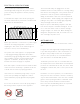
P L E A SE NO T E W HEN A D DING A PA NEL T O T HE G R IL L O R D O O R , A IR F L O W NEED S T O BE TA K EN IN T O C ON SID ER AT ION. SEE IM A G E S 3 A ND 4 . IM A G E 3 Air Flow Out IM A G E 4 Air Flow In 3 7/16 " Approximate distance from bottom of door to bottom of cabinet.
CUS TOM WOOD LOUVER TEMPL ATE 15 IN CH 2 " 7/8 14 3/4" 9" 25/32 Detail A 3 5/8 " Detail B 11/32 " " 11/32 " 1/2" (3 PLCS.) R1/4" (6 PLCS.) 24 IN CH 23 3/4" 18" 2 " 7/8 25/32 Detail A 3 5/8 Detail B " 11/32 " 11/32 " 1/2" (3 PLCS.) D E TA IL A 13/32 R1/4" (6 PLCS.
61 - 67 Stainle ss Steel Equipment C are and Cleaning General Maintenance Condensation S ervice Inform ation Fr eq u e n t ly A s k e d Q u e s t i o n s Warr ant y PRESERVE THE MOMENT® 15 INCH & 24 INCH INSTALL GUIDE 71
S TAINLE SS S TEEL EQUIPMENT C ARE AND CLE ANING C AU T ION: D O NO T U SE A N Y S T EEL WO O L , A BR A SI V E O R CHL O R INE B A SED P R O DUC T S T O CL E A N S TA INL E S S S T EEL SUR FA CE S. STAINLESS STEEL OPPONENTS There are three basic things which can break down your stainless steel’s passivity layer and allow corrosion to rear its ugly head. NO T E: T HE U SE O F S TA INL E S S S T EEL CL E A NER S O R O T HER SUCH S O LV EN T S I S NO T R EC OMMEND ED ON P L A S T IC PA R T S.
G ENER AL M AINTENANCE Keeping the condenser coil clean will minimize required service and lower electrical cost. The condenser coil is accessible from the front. The condenser coil should be cleaned by removing dust and other build-up from the tube assembly with vacuum or a cleaning rag. When properly cleaned you should be able to see through the tube assembly. Warranty does not cover cleaning the condenser coil.
FREQUENTLY A SKED QUES TIONS Q. HOW DO I ADJUST THE TEMPERATURE? A. Refer to True Precision Control ® Operation listed in Table of Contents on page 1. Q. WHY DOES THE EVAPORATOR FAN MOTOR RUN CONSTANTLY? A. This is a normal operation. The evaporator fan motor will run continuously to ensure even temperature throughout your cabinet. This will only stop when the door is opened to keep warm air from being circulated throughout the cabinet. Q. WHY ISN’T MY UNIT COOLING PROPERLY? A.
Q. CAN I PUT 2 UNITS FLUSH AGAINST EACH OTHER WITHOUT SPACING? A. Yes, usually. In typical climate controlled temperature/humidity conditions our units can be installed flush against each other. However, if you place your units in a humid, non-climate controlled area, ½ to 1 inch of spacing between the units will help prevent potential condensation buildup. Q. DOES TRUE SELL THE WOOD DOORS ON OVERLAY? A.
BE VER AG E DISPENSER QUES TIONS Q. WHAT TYPE OF TAP SYSTEM CAN BE USED WITH A TRUE UNIT? A. Different tap systems can be used on ¼ barrel short kegs, but low profile taps are not available in the nonsankey variety, and therefore will probably not fit in our dispensers when used with tall kegs. Q. WHERE CAN I GET MY CO2 TANK FILLED? A. C0 2 is available at many sporting good stores as well as paintball stores.
TRUE RESIDENTIAL® SERIES LIMITED WARRANTY STATEMENT LIMITED 30 DAY COSMETIC WARRANTY Stainless steel doors, handles, and shelves are warranted to be free from defective materials or workmanship for a period of thirty (30) days from the date of original retail purchase. Any defects must be reported to the selling dealer within thirty (30) days from the date of original retail purchase. This limited warranty excludes any type of freight / concealed damage.
NOTES 78 TRUE RESIDENTIAL®
NOTES 15 INCH & 24 INCH INSTALL GUIDE 79
NOTES 80 TRUE RESIDENTIAL LINE
CONTACT US w w w.t r ue -r e siden tial.com (6 36)24 0 -24 0 0 • toll free (8 8 8)616 - 878 3 975557 SD · 12.