
USER MANUAL loudspeaker TXD series TQ-230, TQ-308, TQ-310, TQ-315, TQ-445, TQ-425, TQ-115

user manual
QLight™ series
TQ series manual
page 19
MAINTENANCE
If any of the drive units should cease functioning and needs a replacement recone you are advised
to remove the faulty unit from the cabinet and send it to a professional recone service authorised
to recone Turbosound loudspeakers. This will ensure the continued high performance of your
QLight™ series product.
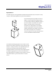
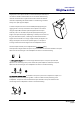
TQ-230 - Removal of the drivers
The grille is secured in place with four flange head screws underneath the grille foam, at the top
and bottom of the cabinet. To remove the grille, remove these screws and lift the grille away from
the cabinet. The 5” woofers can now be removed from the cabinet by undoing the four screws
holding the speaker in place. Disconnect the woofer(s) making note of the polarity for later
reconnection.
To access the high frequency driver, remove the grille as above. Release the high frequency horn
and driver assembly by undoing the four screws securing the horn flange to the baffle.
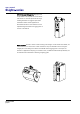
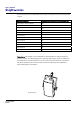
TQ-308/TQ-310/TQ-315 – Removal of the drivers
The grilles on these cabinets are held in place by three countersunk Allen head screws on each
side, accessible from the sides of the cabinet. Remove these screws using the Allen key provided
with your product and lift the grille away from the cabinet. The woofer retaining screws will now
be visible and can be removed. Disconnect the driver(s) making note of the polarity for later
reconnection.
With the grille removed you can now access the HF horn and driver assembly by unscrewing the
four cap head screws securing the horn flange to the baffle. Disconnect the compression driver,
making note of the polarity for later reconnection.
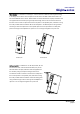
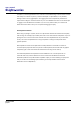
TQ-445 - Removal of the 12”/1” driver
Unscrew the eight countersunk screws from the two vertical battens that hold the protective grille
in place. Be careful when removing the grille as it is under tension and may spring outwards when
released. Set the battens, grille and fixing screws aside for later re-assembly.
Undo the eight M6 x 30mm Allen head bolts holding the driver in place and carefully pull it out
and away from the cabinet. WARNING - this unit is heavy! You will notice that the 1” high
frequency driver is attached to the back of the 12” low frequency driver by its screw adapter.
Disconnect the cables from both HF and LF units and completely remove the driver assembly from
the cabinet. Make a note of the driver polarity for later reconnection.
Separate the drive units by unscrewing the high frequency driver anti-clockwise and lift it away
from the low frequency driver. Depending on which section needs servicing, the appropriate drive