- DIGITAL PROPORTIONAL RADIO CONTROL SYSTEM INSTRUCTION MANUAL -
Thank you for purchasing our product, an ideal radio system for beginners or experienced users alike. Read this manual carefully before operation in order to ensure your safety, and the safety of others or the safe operation of your system. If you encounter any problem during use, refer to this manual first. If the problem persists, contact your local dealer or visit our service and support website for help: Hobbyking.
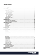
Table of contents 1. Safety .....................................................................................................................................................3 1.1 Safety Symbols ......................................................................................................................................................3 1.2 Safety Guide..................................................................................................................................................
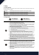
1. Safety 1.1 Safety Symbols Pay close attention to the following symbols and their meanings. Failure to follow these warnings could cause damage, injury or death. Danger · Not following these instructions may lead to serious injuries or death. Warning · Not following these instructions may lead to major injuries. Attention · Not following these instructions may lead to minor injuries. 1.
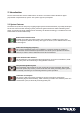
2. Introduction The TGY-i6S transmitter and TGY-iA6B receiver constitute a 10 channel 2.4GHz AFHDS 2A digital proportional computerized R/C system. This system supports quadcopters. 2.1 System Features The AFHDS 2A (Automatic Frequency Hopping Digital System Second Generation) is specially developed for all radio control models.
2.
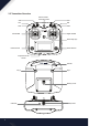
2.2.1 Transmitter Antenna Precautions: • • For best signal quality, make sure that the antenna is at about a 90 degree angle to the model. Do not point the antenna directly at the receiver. Never grip the transmitter antenna during operation. It significantly degrades the RF signal quality and strength and may cause loss of control. 2.2.2 Status Indicator The status indicator is used to indicate the power and working status of the transmitter. • • • Off: the transmitter is powered off.
2.4 USB Simulator Mode The system may be used as a HID controller when connected to a computer via USB. When connected to a computer the function is activated automatically and will be recognized by windows as a game controller. To calibrate or test the system in windows: • • • 1. Type "RUN" into the search bar and select the program. 2. Type "joy.exe" into the "Open:" box and press enter. 3. Select the system and open properties within the game controller menu.
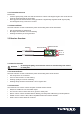
3. Getting Started Before operation, install the battery and connect the system as instructed below. 3.1 Transmitter Battery Installation Danger · Only use specified battery. Danger · Do not open, disassemble, or attempt to repair the battery. Danger · Do not crush/puncture the battery, or short the external contacts. Danger · Do not expose to excessive heat or liquids. Danger · Do not drop the battery or expose to strong shocks or vibrations.
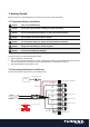
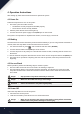
4. Operation Instructions After setting up, follow the instructions below to operate the system. 4.1 Power On Follow the steps below to turn on the system: 1. 2. 3. Check the system and make sure that: • The batteries are fully charged and installed properly. • The receiver is off and correctly installed. Hold the power buttons until screen lights up. Connect the receiver power supply to the B/VCC port on the receiver. The system is now powered on. Operate with caution, or serious injury could result.
5. Home Screen The home screen displays useful information about your model, including timers and TX/RX status. Start Page TX/RX Battery Status + Battery Setup Menu Timers + Timer Menu Main Menu Display Servos Press and hold the screen to perform a servo test. Note: Make sure that the engines are turned off/disconnected during this test. Failure to do so could lead to harm to yourself or others. Display Sensors The system's navigation is designed to be easy and quick.
5.1 Timers To enter the timer function touch T1/T2 on the main screen. The system has 2 timers available, both can be assigned to a switch and have 3 different settings. Setup: 11 1. Select a mode. Modes: • Up: The up timer starts from zero and counts up. • Down: The down timer starts from a pre-selected time and counts down. • D/U(Down then up): The D/U timer starts from the set time, and counts down to 0, then counts back up. 2.
6. Function Settings 6.1 Reverse The reverse function changes a channels direction of movement in relation to its input. For example, if the blades are spinning in the wrong direction, pushing the model into the ground instead of taking off, this function can be used to correct this. Setup: To change between normal and reverse touch the box to the right side of the desired channel. Nor = Normal, Rev = Reverse. Select the icon to save and return to the previous menu. 6.
6.4 Subtrim Subtrim changes the center point of the channel. For example, if a model is always drifting to one side, the subtrim can be used to fix this. To set the subtrim function: To change the subtrim: 1. Touch the box to the right of the desired channel. 2. Select the correct decimal and use the up and down arrow keys. 3. Press the 4. Select the or to confirm or cancel changes. icon to save and return to the previous menu. 6.5 Trims To activate trim select trims in the menu.
• Neg: Changes how much the slave will move in relation to the master in a negative movement. At 50% when the master moves to 100% of its negative motion, the slave will move to negative 50%. Setup: 1. 2. 7. If the mix is not already disabled turn it off by touching the box labeled "on". Select a master by touching the box to the right of the master channel and choose a channel from the list. Select a slave by touching the box to the right of the slave channel, then choose a channel from the list.
6.8 Bri./Sound This function controls screen brightness and volume for the system. To make changes to brightness or volume touch and drag the black box located within the relevant slider. Then select the icon to save and return to the previous menu. 6.9 Output Mode The system has four output modes, PWM 、 PPM、i-BUS and S-BUS compatible. To change between the modes touch the desired mode, the currently selected mode will have a black dot within the circle beside it.
6.11 Select Model The system stores up to 5 different model presets which can be recalled, quickly and easily. To select a model: 1. Touch the model number displayed in a black box. 2. The system will now display the ID menu, use the on-screen up and down arrow keys to navigate to the desired model. 3. Press the to confirm or to cancel. 6.12 Model Reset To reset the current model select model reset from the settings menu and select “Y” for yes. To cancel press “N”. 6.
7. Product Specification 7.1 Transmitter Specification (TGY-i6S) Channels 10 Model type Quadcopter RF range 2.408 ~ 2.475 GHz Bandwidth 500 KHz RF channel 135 RF power Less than 20 dBm 2.4GHz system AFHDS 2A Modulation type GFSK Stick resolution 4096 Low voltage alarm Yes (lower than 4.2V) DSC port Micro USB /PPM Power input 4.2V - 6.
8.
9. Appendix 1 FCC Statement This equipment has been tested and found to comply with the limits for a Class B digital device pursuant to part 15 of the FCC rules. These limits are designed to provide reasonable protection against harmful interference in a residential installation. This equipment generates, uses and can radiate radio frequency energy and, if not installed and used in accordance with the instructions, may cause harmful interference to radio communications.