
i6S TX Manual


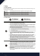
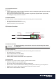

2.2.1 Transmitter Antenna
Precautions:
• For best signal quality, make sure that the antenna is at about a 90 degree angle to the model. Do not
point the antenna directly at the receiver.
• Never grip the transmitter antenna during operation. It significantly degrades the RF signal quality
and strength and may cause loss of control.
2.2.2 Status Indicator
The status indicator is used to indicate the power and working status of the transmitter.
• Off: the transmitter is powered off.
• Blue light: the transmitter is on and working.
• Flashing: low battery or low signal alarm.
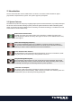
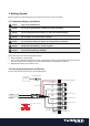
2.3 Receiver Overview
Status Indicator
Update Indicator
CH 2 - 6
PPM/CH1
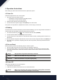
2.3.1 Receiver Antenna
Attention
· For best signal quality, ensure that the receiver is mounted away from motors
or metal parts.
2.3.2 Status Indicator
The status indicator is used to indicate the power and working status of the receiver.
• Off: the power is not connected.
• Lit in red: the receiver is on and working.
• Flashing quickly: the receiver is binding.
• Flashing slowly: the bound transmitter is off or signal is lost.
2.3.3 Connectors
The connectors are used to connect the parts of model and the receiver.
• PPM/CH1: doubles as CH1 and a PPM output.
• CH2 to CH6: used to connect the servos, power or other parts.
• B/VCC: used to connect the bind cable for binding, and the power cable during normal operation.
• SERVO: used to connect i-Bus/S-BUS compatible module and extend channels.
• SENS: used to connect all kinds of sensors.
B/VCC
Antenna