Tank GT25 B5381 Service Engineer’s Manual
Table of Contents Chapter 1:Overview 1.1 1.2 1.3 1.4 About the Transport GT25 B5381 . . . . . . . . . . . . . . . . . . . . . . . . . 1 Features . . . . . . . . . . . . . . . . . . . . . . . . . . . . . . . . . . . . . . . . . . . . . . 2 Unpacking . . . . . . . . . . . . . . . . . . . . . . . . . . . . . . . . . . . . . . . . . . . . 4 1.3.1 Opening the Box . . . . . . . . . . . . . . . . . . . . . . . . . . . . . . . . . 4 1.3.2 Box Contents . . . . . . . . . . . . . . . . . . . . . . . . . . . . . . .
3.5 3.6 3.7 3.8 3.9 Replacing the Slim CD-ROM . . . . . . . . . . . . . . . . . . . . . . . . . . . . 42 Replacing the LED Control Board . . . . . . . . . . . . . . . . . . . . . . . . 44 Replacing the M1012 Adapter Board . . . . . . . . . . . . . . . . . . . . . . 46 3.7.1 M1012 Adapter Board Features for B5381 . . . . . . . . . . . . 48 3.7.2 System Fan Layout . . . . . . . . . . . . . . . . . . . . . . . . . . . . . . 49 3.7.3 M1012 Adapter Board Connector Pin Definition . . . . . . .
PREFACE Copyright This publication, including all photographs, illustrations, and software, is protected under international copyright laws, with all rights reserved. Neither this manual, nor any material contained herein, may be reproduced without written consent of the manufacturer-. Copyright 2006 Version 1.0 Disclaimer Information contained in this document is furnished by TYAN Computer Corporation and has been reviewed for accuracy and reliability prior to printing.
Federal Communications Commission (FCC) Notice for the USA Compliance Information Statement (Declaration of Conformity Procedure) DoC FCC Part 15: This device complies with part 15 of the FCC Rules Operation is subject to the following conditions: 1) This device may not cause harmful interference, and 2) This device must accept any interference received including interference that may cause undesired operation.
About this Manual This manual provides you with instructions on installing your Tank GT25. This manual is intended for experienced users and integrators with hardware knowledge of personal computers. This manual consists of the following parts: Chapter 1: Provides an introduction to the GT25 B5381 barebones, packing list, describes the external components, gives a table of key components, and provides block diagrams of the system.
SAFETY INFORMATION Before installing and using the Tank GT25, take note of the following precautions: iv – – – Read all instructions carefully. – Only use the power source indicated on the marking label. If you are not sure, contact the power company. – The unit uses a three-wire ground cable, which is equipped with a third pin to ground the unit and prevent electric shock. Do not defeat the purpose of this pin.
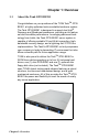
Chapter 1: Overview 1.1 About the Tank GT25 B5381 Congratulations on your purchase of the TYAN TankTM GT25 B5381, a highly-optimized rack-mountable barebone system. The Tank GT25 B5381 is designed to support dual Intel® Dempsey and Woodcrest processors, providing a rich feature set and incredible performance.
1.2 Features Enclosure • Industry 19” rack-mountable 1U chassis storage bay – (4) 3.5” HDD bays – (1) slim line DVD-ROM bay – (1) slim line FDD bay • Dimensions: D 27.87 x W 17.17 x H 1.71 inch (708x436x43.
Motherboard • TYAN S5381 system board • Customized 15”x16” (381x406mm BIOS • PHOENIX BIOS on 8Mbit LPC Flash ROM • Serial console redirect • Supports APM 1.2 and ACPI 2.0 • PnP, DMI 2.0, WfM 2.0 power management Server Management • System fan speed control and monitoring • Chassis intrusion alert • Supports Tyan Server Management (TSM) • TYAN SMDC, IPMI 2.
1.3 Unpacking This section describes the Tank GT25 B5381 package contents and accessories. 1.3.1 Opening the Box Open the box carefully and ensure that all components are present and undamaged. The product should arrive packaged as illustrated below.
1.3.
Component Description M1210 Adapter board M5002 Note: In the future, an FPC cable, as shown below, will be supplied instead of the M5002.
1.3.3 Accessories If any items are missing or appear damaged, contact your retailer or browse to TYAN’s website for service: http://www.tyan.com. The Web site also provides information on other TYAN products, plus FAQs, compatibility lists, BIOS settings, and more.
Rail Kit Mounting Bracket x 4 Sliding Rail x 2 Screw Kit Sliding Brackets Front L-Bracket x 2 Rear L-Bracket x 2 FDD Kit FDD Backplane Cable FDD Cable FDD Rails & Screws 8 Chapter 1: Overview
1.4 About the Product The following views show you the product. 1.4.1 Front View Reset switch Warning LED NMI switch HDD activity LED ID Switch DVD-ROM Drive USB ports Power LED ID LED Power switch 2 x LAN LEDs Hard Drive Bay x 4 1.4.
Case B (Redundant Power) COM1 VGA Port Port PS/2 Keyboard Port USB Ports PCI-E Slot PCI-X Slot ID LED ID Switch Power Supply Sockets Power Supply Fans SAS B5381G25W4H (Optional) LAN Port (NIC2) LAN Port (NIC1) 1.4.
Rear I/O LED *Right or Left is viewed from the rear.
1.4.4 Internal View Case A - Single Power 1 2 3 4 5 6 7 8 12 9 11 1. 2. 3. 4. Power Supply SAS Connector Link Bar Fully Buffered DIMM Memory Slots 5. Fully Buffered DIMM Memory Slots 6. CPU Sockets 12 10 7. 8. 9. 10. 11. 12.
Case B - Redundant Power 1 2 3 4 5 6 7 12 8 9 11 1. 2. 3. 4. Power Supply SAS External Connector Link Bar CPU2 Fully Buffered DIMM Memory Slots 5. CPU1 Fully Buffered DIMM Memory Slots 6. CPU Sockets Chapter 1: Overview 10 7. 8. 9. 10. 11. 12.
1.4.
1.4.6 Motherboard Layout 1 19 18 17 2 16 15 3 14 4 13 5 6 7 12 1. 2. 3. 4. 5. 6. 7. 8. 9. 10. 11 DIMM Slots TEMP Sensor CPU1 CPU2 SATA Connector SAS 2 Connector FPIO Connector Power Connector Buzzer Debug LED Chapter 1: Overview 10 9 8 11. PCI-X Slot 12. ID LED 13. ID SW 14. USB 15. LAN 2 16. LAN 1 17. VGA Port 18. COM1 Port 19.
Jumpers & Connectors Jumper /Connector 16 Function JP1 Clear CMOS Jumper (Close 1-2) Default (Close 2-3) Clear CMOS CN4 SMDC Connector SAS 2 SAS Connector J8 SATA Connector J11 Front Panel Connector Chapter 1: Overview
NOTE Chapter 1: Overview 17
Chapter 2: Setting Up 2.0.1 Before You Begin This chapter explains how to install the CPU, CPU heatsink, memory modules, and hard drives. Instructions on inserting a PCI card are also given. Take note of the precautions mentioned in this section when installing your system. 2.0.2 Work Area Make sure you have a stable, clean working environment. Dust and dirt can get into components and cause malfunctions. Use containers to keep small components separated.
2.0.4 Precautions Components and electronic circuit boards can be damaged by discharges of static electricity. Working on a system that is connected to a power supply can be extremely dangerous. Follow the guidelines below to avoid damage to the Tank GT25 or injury to yourself. • Ground yourself properly before removing the top cover of the system. Unplug the power from the power supply and then touch a safely grounded object to release static charge (i.e. power supply case).
2.1 Rack Mounting After installing the necessary components, the Tank GT25 can be mounted in a rack using the supplied rack mounting kit. Rack mounting kit Sliding Rails x 2: Sliding Brackets x 4 (Front x 2, Rear x 2) Mounting Ears x 2 Screws Kit x 1 Mounting Brackets x 4 2.1.1 Installing the Server in a Rack Follow these instructions to mount the GT25 into an industry standard 19" rack.
Installing the Inner Rails to Chassis 1. Screw the mounting ear to each side of GT25 as shown using 2 screws from the supplied screws kit. Mounting Ears 2. Draw out the inner rails from rail assembly. Install inner rails to left and right sides of chassis using 2 M4-5L(D) screws for each side. Installing Outer Rails to the Rack 1. Measure the distance between inner side of the front and rear mounting brackets in the rack.
2. Locate the front and rear brackets. Rear Bracket x2 Front Bracket x2 3. Reserve 90mm for GT25 on the front bracket. Secure the front bracket to outer rail with 2 M4-4L(C) screws. 4. Reserve the distance same as in Step 2 on rear bracket. Secure the rear bracket to outer rail with 2 M4-4L(C) screws.
5. Secure the outer rail to the rack using 2 brackets and 4 M4-8L(E) screws for each side (A). Secure the mounting brackets from inside, not outside, of the rack (B).
Rackmounting the Server 6. Draw out the middle rail to the latch position. 7. Lift the chassis and then insert the inner slide rails into the middle rails. 8. Push the chassis in and press the latch key (A). Then push the whole system into the rack (B).
9. Secure the mounting ears of chassis to the rack with 2 M4-15L(F) screws. Note: To avoid injury, it is strongly recommended that two people lift the GT25 into the place while a third person screws it to the rack.
2.2 Installing Motherboard Components This section describes how to install components on to the motherboard, including CPU, memory modules, and PCI card. 2.2.1 Removing the Chassis Cover Follow these instructions to remove the Tank GT25 chassis cover. 1. Remove the screw on the back side. Then slide the chassis cover in the direction of arrow. 2. Remove the cover.
2.2.2 Installing the Memory Follow these instructions to install the memory modules on the motherboard. Note: There are 12 DIMM memory slots available. When installing RAM in both slots, begin installation from DIMM1 and install in sequence according to the slot number. 1. Remove the air duct covering the memory slots as shown. 2. Locate the memory slots on the motherboard. 3. Press the memory slot locking levers in the direction of the arrows as shown in the following illustration.
4. Align the memory module with the slot. When inserted properly, the memory slot locking levers lock automatically onto the indentations at the ends of the module. For optimal system operation, please install memory in pairs.
2.2.3 Installing the CPU and Heatsink 1. Follow these instructions to install CPU1, CPU2 and the CPU heatsink. 2. Locate the CPU sockets. CPU1 CPU2 3. Unlatch the CPU lever to release the CPU cover.
4. Pull the lever arm up to unlock the CPU cover. 5. Gently lift up the cover. 6. Place the CPU in the CPU socket, ensuring that Pin 1 is correctly aligned.
7. Close the cover and attach the latch to secure. 8. Align the heatsink screw holes with the holes on the motherboard and insert heatsink screws as shown. 9. Secure the heatsink to the motherboard using four screws. 10. Replace the steps above to install a second CPU and reattach the link bar.
2.2.4 Installing the PCI-X Card Follow these instructions to install a PCI-X card. 1. Push the tab of PCI-X slot on the rear panel in the direction as shown to release the I/O shield. 2. Move the I/O shield to right as shown and take off the I/O shield. 3. Insert the PCI-X card in the slot as indicated. 4. Replace the I/O shield and reattach the slot latch.
2.3 Installing the External Hard Drive The GT25 chassis kit supports external SATA/SAS hard drives. Follow these instructions to install an external SATA or SCSI hard drive. 1. Press the locking lever latch in the direction of arrow (A) and then pull the locking lever open (B). B A 2. Slide the drive tray out. 3. Place a hard drive into the drive tray and turn the tray over.
4. Using 4 HDD screws to secure the HDD. 5. Reinsert the drive tray into the chassis (A), ensuring that the drive tray is completely inserted into the chassis (B). A B 6. Pressing the locking lever to secure the hard drive tray.
2.4 Installing the Slim FDD (Optional) 1. Locate the two FDD rails and screws from the FDD kit. Secure the two rails to the FDD using four screws. FDD Rails & Screws 2. Connect the FFC cable to the FDD. 3. Using a screw driver to pull open the door of the FDD tray.
4. Insert FDD module into the tray. 5. Connect the FFC cable to the connector on the M1210 adapter board. 6. Locate the FDD cable from FDD kit. Connect the wrinkle side to the connector on M1210 adapter board.
NOTE 38 Chapter 2: Setting Up
Chapter 3: Replacing Pre-Installed Components 3.1 Introduction This chapter explains how to replace pre-installed components including the motherboard, LED control board, HDD, and DVD-ROM drive. Take note of the precautions in this section when installing your system. 3.1.1 Work Area Make sure you have a stable, clean working environment. Dust and dirt can get into components and cause malfunctions. Use containers to keep small components separated.
3.1.3 Precautions Components and electronic circuit boards can be damaged by static electricity. Working on a system that is connected to a power supply can be extremely dangerous. Follow the guidelines below to avoid damage to the GT25 or injury to yourself. • Ground yourself properly before removing the top cover of the system. Unplug the power from your computer power supply and then touch a safely grounded object to release static charge (i.e. power supply case).
3.2 Disassembly Flowchart The following flowchart outlines the disassembly procedure.
3.3 Removing the Cover Before replacing any parts you must remove the chassis cover. Follow these instructions to remove the cover of the Tank GT25 chassis cover. 1. Remove the screw on the back side. Then slide the chassis cover in the direction of arrow. 2. Remove the cover.
3.4 Replacing Motherboard Components Follow these instructions to replace motherboard components, including the motherboard. 3.4.1 Disconnecting All Motherboard Cables Before replacing the motherboard or certain components, remove cables connected to the motherboard. Follow these instructions to remove all motherboard cabling. 1. Disconnect all power cables. 2. Disconnect the SAS cable. 3. Disconnect all cables from the front panel, USB, fans, DVD-ROM and SATA connectors.
3.4.2 Removing the Motherboard After removing all of the aforementioned cables, follow these instructions to remove the motherboard from the chassis. 1. Remove the link bar. 2. Remove the fifteen screws securing the motherboard to the chassis. 3. Remove the motherboard.
3.5 Replacing the Slim DVD-ROM Follow these instructions to replace the DVD-ROM. 1. Remove power and data cables from the slim DVD-ROM adapter. 2. Press the tab in the directions as shown to release the DVD-ROM drive. 3. The DVD-ROM drive will be freed from the drive bay after pressing the tab.
4. Remove the two screws that secure DVD-ROM drive to the bracket. 5. Replace the DVD-ROM drive and secure to the bracket using two screws. Then replace the unit into the drive bay and connect the DVD-ROM power and data cables as in steps 1 and 2.
3.6 Replacing the LED Control Board Follow these instructions to replace the LED control board. 1. Remove the two screws securing the LED control board unit to the chassis. 2. Lift the LED control board unit free of the chassis. 3. Remove three screws securing LED control board to the bracket.
4. Lift the LED control board free from the chassis. After replacement, insert the unit into the chassis.
3.7 Replacing the M1210 Adapter Board 1. Remove all of those cables connected to the adapter board, including fan cables, DVD-ROM power cable, front LED panel cable, power cables, and SATA cables. Refer to the photos below for locations.
2. Remove six screws to release the adapter board.
3.7.
3.7.2 System Fan Layout The following table provides the information for system fan layout. System Fan Speed Control Signal M1210 Adapter Board Connect to Motherboard J16 (PWM Signal) Æ J11 (PWM Signal) 3.7.
J3 Chassis Instruction Pin Header 1 INTRU# 2 GND FAN Signal Related Connector Pin Definitions NOTE: The FAN signal naming is based on HW circuit design only. It might be different from the system fan naming.
J6 Fan Connector 1 PWM1 2 VCC12 3 FAN5_TACH 4 GND 5 GND 6 FAN6_TACH 7 VCC12 8 PWM2 J7 Fan Connector 54 1 PWM1 2 VCC12 3 FAN7_TACH 4 GND 5 GND 6 FAN8_TACH 7 VCC12 8 PWM2 Chapter 3: Replacing Pre-Installed Components
J8 Fan Connector 1 PWM1 2 VCC12 3 FAN9_TACH 4 GND 5 GND 6 FAN10_TACH 7 VCC12 8 PWM2 J9 Fan Connector 1 PWM1 2 VCC12 3 FAN11_TACH 4 GND 5 GND 6 FAN12_TACH 7 VCC12 8 PWM2 Chapter 3: Replacing Pre-Installed Components 55
J10 Fan Connector 1 PWM1 2 VCC12 3 FAN13_TACH 4 GND 5 GND 6 FAN14_TACH 7 VCC12 8 PWM2 J1 LCM Connectors 56 1 LCM_+5V 2 LCM_SIN 3 KEY PIN 4 GND 5 LCM_+5VSB 6 LCM_SOUT Chapter 3: Replacing Pre-Installed Components
3.8 Replacing the Redundant to Single Power Supply To replace the power supply follow these instructions. 1. Remove the first row of screws from the top of the power supply casing. Slide the bracket to the right. 2. Remove the second row of screws from the top of the power supply casing. 3. Slide in the power supply unit.
4. Replace the power supply cover and attach to the chassis using five screws as shown. Re-insert the screws in the top of the supply casing as in steps 1 and 2. 5. Re-attach all power cables.
3.8.1 Replacing A Redundant Power Supply 1. Push the power supply unit latch inwards. 2. Pull out the power supply unit as shown. 3. Replace the unit with the new power supply following the steps above in reverse.
Appendix I: BIOS Details The following screenshots display the BIOS details for the B5381 Barebone. Refer to the screenshots for further information on each BIOS screen.
IDE Primary Menu Boot Features Menu 62
Advanced Main Menu Advanced Chipset Control Menu 63
FBD Memory Configuration Menu PCI & PCIE Control Menu 64
USB Control Menu Advanced Processor Control Menu 65
Device Configuration Menu DMI Event Logging Menu 66
Hardware Monitor Menu Voltage Monitoring Menu 67
Fan Speed Monitoring Menu Temperature Monitoring Menu 68
Console Redirection Menu Security Menu 69
Power Menu Boot Menu 70
Exit Menu 71
Appendix II: Cable Connection Tables SAS / SATA Cables Table 1: B5381(with LSI SAS controller) M1210 Adapter Board Connect to Motherboard SAS 1 (J21) Æ SAS Connector (SAS2) SAS 2 (J22) SAS 3 (J23) SAS 4 (J24) Table 2: B5381 (without LSI SAS controller) M1210 Adapter Board Connect to Motherboard SAS 1 (J21) Æ SATA Connector (J8) SAS 2 (J22) SAS 3 (J23) SAS 4 (J24) Power Supply Cables Table 3: Power Supply to Motherboard 72 Power Supply Connect to Motherboard P1 24-pin power cable Æ CN5 2
Table 4: Power Supply to M1210 Adapter Board Power Supply Connect to M1210 P4 4-pin power cable Æ PW1 4-pin connector P5 4-pin power cable Æ PW2 4-pin connector Other Cables Table 5: M1210 Adapter Board to Motherboard M1210 Connect to Motherboard J16 (FPIO_140) connector Æ J1 Table 6: M1003 Front Panel Control Board Related Cable M1003 J1 USB connector M1210 J15 connector Æ Table 7: DVD-ROM Related Cable M1210 IDE1 (DVD-ROM) connector Æ DVD-ROM Backplane M1210 J11 power connector Æ DV
Appendix III: Memory Population Rules Channel Single Dual Four Four Four X X X X X X X DIMM DIMM1 (A0) DIMM2 (A1) DIMM3 (A2) DIMM4 (B0) X X X DIMM5 (B1) X X X X DIMM6 (B2) DIMM7 (C0) X X DIMM8 (C1) X X X X DIMM9 (C2) DIMM10 (D0) X X DIMM11 (D1) X X X X DIMM12 (D2) NOTE: Please always install memory beginning with DIMM1. You can choose to install single, dual or four channel population.
Technical Support If a problem arises with your system, you should first turn to your dealer for direct support. Your system has most likely been configured or designed by them and they should have the best idea of what hardware and software your system contains. Hence, they should be of the most assistance for you.
3. Contact your dealer for help BEFORE calling TYAN. 4. Check the TYAN user group: alt.comp.periphs.mainboard.TYAN Returning Merchandise for Service During the warranty period, contact your distributor or system vendor FIRST for any product problems. This warranty only covers normal customer use and does not cover damages incurred during shipping or failure due to the alteration, misuse, abuse, or improper maintenance of products.