Tiger i7320 S5350 Tiger i7320 User’s Manual /// S5350 Revision 1.00 Copyright © TYAN Computer Corporation, 2004. All rights reserved. No part of this manual may be reproduced or translated without prior written consent from TYAN Computer Corp. All registered and unregistered trademarks and company names contained in this manual are property of their respective owners including, but not limited to the following. TYAN, Tiger i7320 S5350 are trademarks of TYAN Computer Corporation.
Tiger i7320 S5350 Table of Contents Table of Contents Before you begin… .................................................................................................................. v Chapter 1: Introduction......................................................................................................... 1-1 1.1 Congratulations!......................................................................................................... 1-1 1.2 Hardware Specifications ..............................
Tiger i7320 S5350 Table of Contents 3.5 Security .................................................................................................................... 3-20 3.6 Power ....................................................................................................................... 3-21 3.7 Boot.......................................................................................................................... 3-22 3.8 Exit ...........................................................
Tiger i7320 S5350 Table of Contents Chapter 5: Diagnostics ......................................................................................................... 5-1 5.1 Beep Codes ............................................................................................................... 5-1 5.2 Flash Utility................................................................................................................. 5-1 Appendix I: Glossary ......................................................
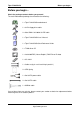
Tiger i7320 S5350 Before you begin… Before you begin… Check the package contents before you proceed.
Tiger i7320 S5350 Chapter 1: Introduction Chapter 1: Introduction 1.1 Congratulations! Congratulations on your purchase of the powerful Dual Intel Xeon processor solution, the Tiger i7320 S5350. Based on Intel E7320 chipset, the S5350 offers exceptional performance. Compatible with EPS12V power supplies, the ATX form factor S5350 features an onboard ATi 8MB PCI RageXL VGA, two Gigabit Ethernet ports, serial ATA, RAID, which provides an advances and versatile solution for your server needs.
Tiger i7320 S5350 • Chapter 1: Introduction Temperature and voltage monitoring Memory • • • Dual memory channels, 8 x DIMM sockets Supports up to eight DDR-266/333 DIMM Registered, ECC/non-ECC memory supported Integrated PCI IDE • • Dual channel master mode support four IDE devices Supports for ATA-100/66/33 IDE drives and ATAPI compliant devices Integrated Serial ATA • • • Two serial ATA host controllers embedded Supports two serial ports running at 1.
Tiger i7320 S5350 Chapter 2: Board Installation Chapter 2: Board Installation 2.1 Installing the Motherboard The Tiger i7320 S5350 motherboard conforms fully to the ATX specification. Before continuing with the installation, confirm that your chassis supports a standard ATX motherboard. If you are unsure, contact your dealer for more information. 2.1.1 Installation Notes This user manual contains important information and you should read it thoroughly before attempting the installation procedure.
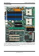
Tiger i7320 S5350 Chapter 2: Board Installation 2.2 Board Image The following is an image of the Tiger i7320 S5350 motherboard. The above photograph is purely representative. Due to engineering updates and new board revisions, certain components may change and or be repositioned. The picture above may or may not look exactly like the board you received. 2-2 http://www.tyan.
Tiger i7320 S5350 Chapter 2: Board Installation 2.3 Block Diagram The following is a block diagram of the Tiger i7320 S5350. 2-3 http://www.tyan.
Tiger i7320 S5350 Chapter 2: Board Installation 2.4 Motherboard Components The diagram below shows the main motherboard components.
Tiger i7320 S5350 Chapter 2: Board Installation 2.5 Jumpers and Connectors The following section gives details of the motherboard pin headers and jumpers and their functions. Pin headers are on-board connectors that can be used to connect the motherboard to peripherals. Jumpers are used to configure the motherboard.
Tiger i7320 S5350 Chapter 2: Board Installation 2.5.
Tiger i7320 S5350 Chapter 2: Board Installation 2.5.
Tiger i7320 S5350 Chapter 2: Board Installation 2.5.6 Chassis Fan Connectors with Fan Control: FAN 1/2/3/4/5 CPUFAN1 1 J1 KB / MS KB(Bottom) Mouse(Top) PW1 FAN7 J4 USB1 Speed Control +12V Tachometer PW2 1 CPU1 J3 (COM1) J2 (VGA) LAN1 BATT Use these headers to connect the chassis cooling fans to your motherboard to keep the system stable and reliable. CPU2 LAN2 Intel E7320 LED1 S5350 These connectors support the tachometer monitoring and auto fan speed control.
Tiger i7320 S5350 Chapter 2: Board Installation 2.5.8 CPU FAN1/FAN2 Connectors +12V CPUFAN1 1 J1 KB / MS KB(Bottom) Mouse(Top) FAN7 J4 USB1 Tachometer Speed Control PW2 PW1 1 CPU1 J3 (COM1) J2 (VGA) LAN1 BATT Speed Control +12V Tachometer CPU2 LAN2 Intel E7320 LED1 S5350 Use these headers to connect the CPU cooling fans to your motherboard to keep the system stable and reliable.
Tiger i7320 S5350 Chapter 2: Board Installation 2.5.10 Chassis Fan Connectors: FAN6, FAN7 CPUFAN1 1 J1 KB / MS KB(Bottom) Mouse(Top) GND +12V PW2 PW1 FAN7 J4 USB1 1 CPU1 J3 (COM1) NC J2 (VGA) LAN1 BATT Use this header to connect the chassis cooling fans to your motherboard to keep the system stable and reliable.
Tiger i7320 S5350 Chapter 2: Board Installation 2.5.12 LAN1/LAN2 activity LED Headers: JP21, JP30 CPUFAN1 1 J1 KB / MS KB(Bottom) Mouse(Top) PW2 PW1 FAN7 J4 USB1 1 JP21 CPU1 J3 (COM1) 1 J2 (VGA) LAN1 BATT Pin 1: LED+ Pin 2: LED- CPU2 LAN2 Intel E7320 LED1 S5350 Use these headers to connect with the front panel activity LEDs for LAN1/LAN2.
Tiger i7320 S5350 Chapter 2: Board Installation 2.5.14 Clear CMOS Jumper: JP25 CPUFAN1 3 1 J1 KB / MS KB(Bottom) Mouse(Top) PW1 FAN7 J4 USB1 PW2 Pin 1-2: Normal (Default) 1 1 CPU1 J3 (COM1) 3 J2 (VGA) LAN1 BATT 1 CPU2 LAN2 Intel E7320 LED1 S5350 Use this jumper when you forgot your system/setup password or need to clear system BIOS setting.
Tiger i7320 S5350 Chapter 2: Board Installation 2.6 Mounting the Motherboard Before installing your motherboard, ensure that your chassis is fully compatible. The Tiger i7320 S5350 motherboard conforms fully to the ATX specification. Your chassis should include preinstalled mounting posts that match exactly with the mounting holes in the motherboard.
Tiger i7320 S5350 Chapter 2: Board Installation 2.6.1 Installing Memory Before installing memory, ensure that the memory you have is compatible with the motherboard and processor. DDR 266/333 modules are required. Check the TYAN Web site at: www.tyan.com for details of the type of memory recommended for your motherboard. The following diagram shows common types of memory modules.
Tiger i7320 S5350 Chapter 2: Board Installation 2.6.2 Memory Installation Procedure Follow these instructions to install memory modules into the Tiger i915 S5350. 1. Press the locking levers in the direction shown in the following illustration. 2. Align the memory module with the socket. The memory module is keyed to fit only one way in the socket. Key slot 3. Seat the module firmly into the socket by gently pressing down until it sits flush with the socket. The locking levers pop up into place. 2.6.
Tiger i7320 S5350 Chapter 2: Board Installation 1. Locate the processor sockets on the motherboard and lift the locking lever as shown. 2. 3. Insert the processor into the socket making sure that pin 1 is correctly located. Return the locking lever to its locked position. Pin 1 4. 5. Repeat this procedure for the second processor socket. Turn the board upside down and insert the heat sink spring mechanism as shown. 6. Turn the board the right way up again and screw the heat sink into place. 7.
Tiger i7320 S5350 Chapter 2: Board Installation 2.7 Installing Drive Cables IDE and FDD connectors are “keyed” to only allow insertion only one way. TYAN motherboards have two on-board IDE channels, each supporting two drives. The black connector is a standard IDE channel. Only the blue connector supports RAID. Insert the IDE cable as shown in the diagram.
Tiger i7320 S5350 Chapter 2: Board Installation 2.8 Installing Expansion Cards Before installing add-in cards, you should ensure that they are fully compatible with your motherboard. For this reason, we’ve provided the diagrams below, showing the expansion slots that appear on your motherboard. Expansion cards should be pushed firmly into the appropriate slot. Excessive force can damage both the card and the motherboard and care should be taken.
Tiger i7320 S5350 Chapter 2: Board Installation 2.9 Installing Optional SO-DIMM modules Your Tiger i7320 (S5350) motherboard may be equipped with an optional proprietary SODIMM connector. The SO-DIMM connector can be used for expansion cards to provide such features as, additional SATA or SCSI support. For details of available expansions cards, visit the TYAN website at http://www.tyan.com. To install a SO-DIMM expansion card: 1. Open the spring levers as shown. 2.
Tiger i7320 S5350 Chapter 2: Board Installation Key slot 2.10 Connecting External Devices Your new motherboard supports a number of different interfaces for connecting peripherals. See the diagram below. Port definitions: A PS2 mouse port (green) B PS2 keyboard port (purple) C USB 2.
Tiger i7320 S5350 2.11 Chapter 2: Board Installation Installing the Power Supply There are two power connectors on your Tiger i7320 S5350. The Tiger i7320 S5350 requires that you have an EPS12V power supply that has a 24-pin and an 8-pin power connector. Please be aware that using of the incompatible power supplies with the board can damage the motherboard and/or CPU(s). Disconnect power supply from electrical outlet 1. Connect the EP12V 8-pin power connector 2.
Tiger i7320 S5350 Chapter 3: BIOS Setup Chapter 3: BIOS Setup 3.1 About the BIOS The BIOS is the basic input/output system, the firmware on the motherboard that enables your hardware to interface with your software. This chapter describes different settings for the BIOS that can be used to configure your system. The BIOS section of this manual is subject to change without notice and is provided for reference purposes only.
Tiger i7320 S5350 Chapter 3: BIOS Setup system manufacturer has carefully chosen the chipset defaults for best performance and reliability. Even a seemingly small change to the Chipset setup options may cause the system to become unstable or unusable. Setup Variations Not all systems have the same BIOS setup layout or options.
Tiger i7320 S5350 Chapter 3: BIOS Setup Boot Use this menu to configure boot options for your system. Exit This contains the various BIOS exit options. 3.3 Main In this section, you can alter general features such as the date and time, as well as access to the IDE configuration options. Note that the options listed below are for options that can directly be changed within the Main Setup screen.
Tiger i7320 S5350 Chapter 3: BIOS Setup 3.3.1 IDE Master / Slave Setup Computer detects IDE drive type from drive C to drive F. Press Enter on any of the Master/Slave options to view advanced details of the corresponding drive. The system displays advanced details like the number of heads/cylinders/sectors on the detected disk and the maximum storage capacity of the disk.
Tiger i7320 S5350 Chapter 3: BIOS Setup drives are no longer specified in terms of classical geometry, but rather in terms of their total number of user data sectors and addressed using LBA. Disabled / Enabled 32 Bit I/O Enables or disables 32 bit data transfer mode. Enabling this option causes the PCI hard disk interface controller to bundle together two 16-bit chunks of data from the drive into a 32-bit group, which is then transmitted to the processor or memory.
Tiger i7320 S5350 Chapter 3: BIOS Setup 3.3.2 Memory Cache This setting allows you to tweak the various cache settings for optimal performance of your system. Press Enter to display the various cache settings. Cache System BIOS Area This feature is only available when the system BIOS is shadowed. It enables or disables the caching of the system BIOS ROM at F0000h-FFFFFh via the L2 cache. This greatly speeds up accesses to the system BIOS.
Tiger i7320 S5350 Chapter 3: BIOS Setup 3.3.3 Boot Features This option allows setting boot parameters. Press Enter to view the Boot Features screen. Summary Screen Enables or disables the display of the summary screen during boot up. When Summary Screen is Enabled (the default), a Phoenix BIOS Setup Utility summary screen appears during system boot after the power-on self-test (POST). The summary screen lists many of the system setup settings.
Tiger i7320 S5350 Chapter 3: BIOS Setup Extended Memory Testing Determines the tests that will be run on extended memory (memory above 1MB) during boot up. Normal / Just zero it / None 3.4 Advanced This section facilitates configuring advanced BIOS options for your system. Installed OS Select the operating system installed on the PC. Note: An incorrect setting can cause the operating system to behave unpredictably.
Tiger i7320 S5350 Chapter 3: BIOS Setup Large Disk Access Mode This option determines whether a hard drive with more than 1024 cylinders, more than 16 heads and or more than 64 tracks per sector is present on the system. Set this option to DOS if such a hard drive is present. Else, set this option to Other. Virtually, all modern hard disks have these characters so leave this option at DOS, unless you know otherwise.
Tiger i7320 S5350 Chapter 3: BIOS Setup 3.4.1 Hardware Monitor This displays critical system parameters like CPU speed, fan speeds, voltage levels and CPU temperature. 3.4.2 Advanced Chipset Control This section allows you to fine tune the chipset configuration.
Tiger i7320 S5350 Chapter 3: BIOS Setup Force Compliance Mode Entry: Enable or Disable PCI-E Compliance mode by setting item to the desired value. Enabled / Disabled DRAM Data Integrity Mode If you have ECC memory modules installed, select the correct ECC mode with this setting. Disabled / 72-bit ECC / 144-bit ECC / Auto ECC Error Type When an ECC error occurs, it generates an interrupt. Select the type of interrupt to report: NMI (Non-Maskable); SMI (System Management); SCI (System Control).
Tiger i7320 S5350 Chapter 3: BIOS Setup 3.4.2.2 Integrated LAN 1 PCI-E port A Device 2: Force PCI Express v1.0 Compatibility Mode this PCI-E Port A by setting item to the desired value. Auto / Disabled / Enabled / Force PCI Express v1.0 Compatibility Mode Option ROM Scan Initialize device expansion ROM Enabled / Disabled 3.4.2.3 Integrated LAN 2 PCI-E port A Device 3: Force PCI Express v1.0 Compatibility Mode this PCI-E Port A by setting item to the desired value.
Tiger i7320 S5350 Chapter 3: BIOS Setup Option ROM Scan Initialize device expansion ROM Enabled / Disabled 3.4.3 Advanced Processor Options This section allows you to fine-tune the processor options. Hyper Threading Technology Enable this only if you have an Intel Hyper Threading processor. Hyper-Threading Technology enables multi-threaded software applications to execute threads in parallel.
Tiger i7320 S5350 • Chapter 3: BIOS Setup thermal monitor’s control circuit, when active, lowers the CPU temperature by throttling the internal CPU clock speed. This is done with a 50% duty-cycle, which means that a 2GHz CPU will then effectively run at a 1GHz clock speed. Due to the fast response time of the thermal monitor circuit (~50ns) the CPU will only be ‘throttled’ for a very brief period.
Tiger i7320 S5350 Chapter 3: BIOS Setup Serial Port B: This defines how the second serial port is detected and configured. Disabled / Enabled Base I/O Address: Set the base I/O address for serial port A. 3F8 / 2F8 / 3E8 / 2E8 Interrupt: Set the interrupt for serial port A. IRQ3 / IRQ4 Mode Set the mode for serial port B. Normal / IrDA / ASK-IR Parallel Port This defines how the parallel port is detected and configured. Disabled / Enabled Mode This field allows the user to select the parallel port mode.
Tiger i7320 S5350 Chapter 3: BIOS Setup Base I/O Address / Interrupt: This determines the base address and interrupt of the parallel port. Disabled / 378/IRQ7 / 278/IRQ5 / 3BC/IRQ7 DMA Channel This BIOS feature determines which DMA channel the parallel port should use when it is in ECP mode. The ECP mode uses the DMA protocol to achieve data transfer rates of up to 2.5 Mbits/s and provides symmetric bidirectional communications. For all this, it requires the use of a DMA channel.
Tiger i7320 S5350 Chapter 3: BIOS Setup 3.4.5 DMA Event Logging Event Logging Select Enabled to allow logging of DMI events Disabled / Enabled ECC Event Logging Select Enabled to allow logging of ECC events Disabled / Enabled Clear all DMI event logs Setting this to ‘Yes’ will clear the DMI event log after rebooting. No / Yes 3-17 http://www.tyan.
Tiger i7320 S5350 Chapter 3: BIOS Setup 3.4.6 Console Redirection Com Port Address If enabled it will use a port on the motherboard. Disabled / On-board COM A / On-board COM B / NULL Baud Rate Enables the specified baud rate. 300 / 1200 / 2400 / 9600 / 19.2K / 38.4K / 57.6K / 115.2K Console Type Enables the specified console type.
Tiger i7320 S5350 Chapter 3: BIOS Setup 3.4.7 ASF Configuration Minimum WatchDog Timeout Time for BIOS to stop the WatchDog timer after a reset has occurred. BIOS Boot Timeout Time for BIOS to boot before the system is reset. OS Boot Timeout Time for OS to boot before the system is reset. Power-on wait time Maximum amount of time for Alert Sending Device (ASD) to establish connection with its transport media. 3-19 http://www.tyan.
Tiger i7320 S5350 Chapter 3: BIOS Setup 3.5 Security These settings allow you to configure the security options for your system. The system displays the current supervisor and user passwords. Set Supervisor Password This option allows the supervisor to set the supervisor password to restrict access to the BIOS settings. Set User Password This option allows the user to set the user password. Password on boot When enabled, the system will ask for a password at every boot.
Tiger i7320 S5350 Chapter 3: BIOS Setup 3.6 Power These settings allow you to configure the power options for your system. Resume On Time When enabled, this allows the system to be woken up at a specified time. This time is specified by the Resume Time parameter. Off / On Power Button Behavior This specifies the behavior of the system after the power button is pressed. • On/Off - This powers on / powers off the system after the power button is pressed.
Tiger i7320 S5350 Chapter 3: BIOS Setup 3.7 Boot Use this screen to select options for the Boot Settings Configuration. 3.8 Exit These settings set the exit options on your system. Exit Saving Changes This exits BIOS setup after saving the changes made. Exit Discarding Changes This exits BIOS setup after discarding the changes made. Load Setup Defaults Loads the factory default values. Discard Changes Discards all changes made without exiting BIOS setup.
Tiger i7320 S5350 Chapter 4: SATA/RAID Setup (for SATA RAID model) Chapter 4: SATA/RAID Setup 4.1 Introduction This section describes the SATA/RAID function of your Tiger i7320 and how to configure your system. This section also covers Intel Application Accelerator RAID Edition software and its configuration. Your new Tyan Tiger i7320 S5350 features an integrated serial ATA controller which supports two serial ports running at 1.5 Gb/s with support for RAID 0 or 1. 4.
Tiger i7320 S5350 Chapter 4: SATA/RAID Setup (for SATA RAID model) 4.2.3 RAID migration feature Intel® Application Accelerator RAID Edition features is an advanced software technology called RAID migration that enables a properly configured PC, known as a “RAID Ready” system, to be converted to a high-performance RAID 0 or RAID 1configuration just by adding a Serial ATA hard drive to the system and invoking the RAID migration process.
Tiger i7320 S5350 Chapter 4: SATA/RAID Setup (for SATA RAID model) 4.5.1 Creating, Deleting, and Resetting RAID Sets Note Please refer to Section 4.7 for illustration examples of the Intel RAID Option ROM windows. The Serial ATA RAID set must be configured in the RAID Configuration utility.
Tiger i7320 S5350 Chapter 4: SATA/RAID Setup (for SATA RAID model) 4.5.4 Reset RAID Data Note Please refer to Section 4.7 for illustration examples of the Intel RAID Option ROM windows. Warning All data on the RAID drives and any internal RAID structures will be lost. 1. Select option 3 Reset Disks to Non-RAID and press the key to delete the RAID set and remove any RAID structures from the drives. 2. Confirm the selection by pressing the key. 4.
Tiger i7320 S5350 Chapter 4: SATA/RAID Setup (for SATA RAID model) 4.6.2 Installation Using F6 Method When you start the installation of Windows* XP, you most likely will be presented with a message stating, ‘Setup could not determine the type of one or more mass storage devices installed in your system’. If this occurs, the instructions below document how to install the RAID driver.
Tiger i7320 S5350 Chapter 4: SATA/RAID Setup (for SATA RAID model) 4.7.3 Using the Intel RAID Option ROM Creating, Deleting, and Resetting RAID Volumes The Serial ATA RAID volume may be configured using the RAID Configuration utility stored within the Intel RAID Option ROM. During the Power-On Self Test (POST), the following message will appear for a few seconds: Note The ‘Drive Model’, ‘Serial #’, and ‘Size’ listed in your system can differ from the following example.
Tiger i7320 S5350 Chapter 4: SATA/RAID Setup (for SATA RAID model) 1. Select option 1 ‘Create RAID Volume’ and press the key and the following window will appear: Intel (R) RAID for Serial ATA - RAID Configuration Utility Copyright (C) 2003-04 Intel Corporation. All Rights Reserved. v3.6.0.6277 [ CREATE ARRAY MENU ] Name: RAID_Volume1 RAID Level: RAID0(Stripe) Strip Size: 128KB Capacity: 465.
Tiger i7320 S5350 Chapter 4: SATA/RAID Setup (for SATA RAID model) Intel (R) RAID for Serial ATA - RAID Configuration Utility Copyright (C) 2003-04 Intel Corporation. All Rights Reserved. v3.6.0.6277 [ CREATE ARRAY MENU ] Name: RAID_Volume1 RAID Level: RAID0(Stripe) Strip Size: 128KB Capacity: 465.7 GB Create Volume [ HELP ] Press "ENTER" to Create the specified volume. [ ]-Change [TAB]-Next [ESC]-Previous Menu [ENTER]-Select ║ 6.
Tiger i7320 S5350 Chapter 4: SATA/RAID Setup (for SATA RAID model) Intel (R) RAID for Serial ATA - RAID Configuration Utility Copyright (C) 2003-04 Intel Corporation. All Rights Reserved. v3.6.0.6277 [ MAIN MENU ] 1. Create RAID Volume 2. Delete RAID Volume 3. Reset Disks to Non-RAID 4. Exit [ DISK/VOLUME INFORMATION ] RAID Volumes: ID Name Level Strip Size Status 0 RAID_Volume1 RAID0(Stripe) N/A 232.8GB Normal WDC WD2500JD-00F WD-WMAEH2201346 Port0 232.
Tiger i7320 S5350 Chapter 4: SATA/RAID Setup (for SATA RAID model) Delete RAID Volume Warning By performing this operation, all data on the RAID drives will be lost. 1. Select option 2 ‘Delete RAID Volume’ from the main menu window and press the key to select a RAID volume for deletion. The following window will appear: Warning If your system currently boots to RAID and you delete the RAID volume in the Intel RAID Option ROM, your system will become unbootable.
Tiger i7320 S5350 Chapter 4: SATA/RAID Setup (for SATA RAID model) Intel (R) RAID for Serial ATA - RAID Configuration Utility Copyright (C) 2003-04 Intel Corporation. All Rights Reserved. v3.6.0.6277 [ DELETE ARRAY MENU ] Name Level VOLUME DELETE Drives VERIFICATION Capacity Status Bootable RAID_Volume1 Are RAID0(Stripe) 465.
Tiger i7320 S5350 Chapter 4: SATA/RAID Setup (for SATA RAID model) 4.8 Installing the Intel Application Accelerator RAID Edition 4.8.1 Installation Caution Warning The Intel Application Accelerator RAID Edition driver may be used to operate the hard drive from which the system is booting or a hard drive that contains important data.
Tiger i7320 S5350 Chapter 4: SATA/RAID Setup (for SATA RAID model) Installation: Welcome Screen Click on the ‘Next’ button after the following welcome window appears: Installation: License Agreement Carefully read through the license agreement in the following window and if you accept all the terms, click on the ‘Yes’ button: Installation: Choose Destination Location Select the folder in the following window where you would like Setup to install the files and then click on the ‘Next’ button: 4-13 http:
Tiger i7320 S5350 Chapter 4: SATA/RAID Setup (for SATA RAID model) Installation: Select Program Folder Select a program folder in the following window where you would like Setup to add the program icons: Installation: Setup Status The status of the Intel Application Accelerator RAID Edition Setup will then appear in the following window: 4-14 http://www.tyan.
Tiger i7320 S5350 Chapter 4: SATA/RAID Setup (for SATA RAID model) Installation: InstallShield(R ) Wizard Complete Once installation is complete, the following window will appear: 4.9 Confirming the Intel Application Accelerator RAID Edition is Installed 4-15 http://www.tyan.
Tiger i7320 S5350 Chapter 4: SATA/RAID Setup (for SATA RAID model) To confirm that the Intel Application Accelerator RAID Edition has been installed, complete the following steps: • Click on Start Button / All Programs • Find the ‘Intel Application Accelerator RAID Edition’ program group • Select the ‘Intel Application Accelerator’ shortcut • The Intel Application Accelerator RAID Edition utility should be shown If installation was done via have-disk, F6, or unattended installation methods, you can confir
Tiger i7320 S5350 • Chapter 4: SATA/RAID Setup (for SATA RAID model) Then look for a parameter in the Parameters list box titled ‘Driver Version’. This should have a version number in the following format: 3.6.0.xxxx 4.10.2 RAID Driver File Properties: • • • • Locate the file “iaStor.sys” within the following path: \Windows\System32\Drivers Right click on “iaStor.
Tiger i7320 S5350 Chapter 4: SATA/RAID Setup (for SATA RAID model) 4.12.2 “RAID Ready” System Requirements In order for a system to be considered “RAID Ready”, it must meet all of the following requirements: 1. System with a supported Intel chipset (currently a chipset with an Intel® 6300ESB I/O Controller Hub) and one Serial ATA (SATA) hard drive 2. Motherboard BIOS that includes the Intel RAID Option ROM 3. Intel Application Accelerator RAID Edition 4. RAID Controller enabled in the BIOS 4.12.
Tiger i7320 S5350 Chapter 4: SATA/RAID Setup (for SATA RAID model) 1. Create a new partition using Windows Disk Management or 2. Extend the partition to fill the rest of the available space. Windows does not natively include tools to do this, but there are 3rd party software utilities to accomplish this such as PartitionMagic* or Partition Commander*.
Tiger i7320 S5350 Chapter 4: SATA/RAID Setup (for SATA RAID model) Note The ‘Physical Disks’ listed in your system can differ from the following illustration. 4.13.1 Create RAID Volume from Existing Hard Drive To create a RAID volume from an existing disk, right-mouse click on ‘Actions’ and select ‘Create RAID Volume From Existing Hard Drive’ to create a new RAID volume as illustrated below: 4-20 http://www.tyan.
Tiger i7320 S5350 Chapter 4: SATA/RAID Setup (for SATA RAID model) Note Note: Creating a RAID volume from an existing disk can also be accomplished by clicking on the ‘Actions’ file menu, and then arrow down and click on 'Create RAID Volume from Existing Hard Driver'.
Tiger i7320 S5350 4KB 8KB 16KB 32KB 64KB 128KB Chapter 4: SATA/RAID Setup (for SATA RAID model) For specialized usage models requiring 4KB strips For specialized usage models requiring 8KB strips Best for sequential transfers Good for sequential transfers Good general purpose strip size est performance for most desktops and workstations Create RAID Volume from Existing Hard Drive Wizard Confirm Creation of New RAID Volume Confirm the creation of the new RAID volume and then click ‘Next’: 4-22 http://www.
Tiger i7320 S5350 Chapter 4: SATA/RAID Setup (for SATA RAID model) 4.13.2 Migration Process May Take Considerable Time to Complete The migration process may take up to two hours to complete depending on the size of the disks being used and the strip size selected. A dialog window will appear stating that the migration process may take considerable time to complete and you must click ‘Finish’ in order to start the migration.
Tiger i7320 S5350 Chapter 4: SATA/RAID Setup (for SATA RAID model) Note The time remaining for your system can differ from the following example. If the migration process was completed successfully, you will need to reboot your system to use the entire volume capacity. Note You must reboot your system in order to use the full capacity of the new volume. 4.14 Uninstalling the Intel Application Accelerator RAID Edition 4.14.
Tiger i7320 S5350 Chapter 4: SATA/RAID Setup (for SATA RAID model) 2. Depending on your system configuration, complete one of the following set of tasks: If System has Intel RAID Option ROM Installed: a. Enter the Intel RAID Option ROM Setup by pressing the 'Ctrl' and 'i' (CTRL + i) keys at the appropriate time during boot-up. (Note: If your system does not appear to have Intel RAID Option ROM installed, skip to step '2d' below) b.
Tiger i7320 S5350 Chapter 4: SATA/RAID Setup (for SATA RAID model) 4.16.2 Create Volume Manually The Intel Application Accelerator RAID Edition offers the ability to create a RAID volume. This option should be used if you are using a third bootable device such as an IDE or SCSI hard drive – in addition to using two Serial ATA hard drives. One benefit of using a third bootable device and creating a RAID volume is that the operating system is not located on the RAID volume.
Tiger i7320 S5350 Chapter 4: SATA/RAID Setup (for SATA RAID model) RAID Volume Name: A desired RAID volume name needs to be typed in where the ‘RAID_Volume1’ text currently appears above. The RAID volume name has a maximum limit of 16 characters. The RAID volume name must also be in English alphanumeric ASCII characters. RAID Level: Select the desired RAID level: RAID 0 (Performance) – A volume optimized for performance will allow you to access your data more quickly.
Tiger i7320 S5350 Chapter 4: SATA/RAID Setup (for SATA RAID model) Confirm Creation of New RAID Volume Confirm the creation of the new RAID volume and then click ‘Next’: 4.16.3 Successful Creation If the manual volume creation process was completed successfully, the following dialog window will appear: 4-28 http://www.tyan.
Tiger i7320 S5350 Chapter 4: SATA/RAID Setup (for SATA RAID model) 4-29 http://www.tyan.
Tiger i7320 S5350 Chapter 5: Diagnostics Chapter 5: Diagnostics Note: if you experience problems with setting up your system, always check the following things in the following order: Memory, Video, CPU By checking these items, you will most likely find out what the problem might have been when setting up your system. For more information on troubleshooting, check the TYAN website at: http://www.tyan.com. 5.
Tiger i7320 S5350 Appendix I: Glossary Appendix I: Glossary ACPI (Advanced Configuration and Power Interface): a power management specification that allows the operating system to control the amount of power distributed to the computer’s devices. Devices not in use can be turned off, reducing unnecessary power expenditure. AGP (Accelerated Graphics Port): a PCI-based interface which was designed specifically for demands of 3D graphics applications.
Tiger i7320 S5350 Appendix I: Glossary Cache size: refers to the physical size of the cache onboard. This should not be confused with the cacheable area, which is the total amount of memory which can be scanned by the system in search of data to put into the cache. A typical setup would be a cache size of 512KB, and a cacheable area of 512MB. In this case, up to 512KB of the main memory onboard is capable of being cached. However, only 512KB of this memory will be in the cache at any given moment.
Tiger i7320 S5350 Appendix I: Glossary EMRL: Embedded RAID Logic. An Adaptec specific RAID technology. ESCD (Extended System Configuration Data): a format for storing information about Plugn-Play devices in the system BIOS. This information helps properly configure the system each time it boots. Fault-tolerance: a term describing a system where one component can quickly be replaced without causing a loss of service, such as in a RAID system. Firmware: low-level software that controls the system hardware.
Tiger i7320 S5350 Appendix I: Glossary Latency: the amount of time that one part of a system spends waiting for another part to catch up. This is most common when the system sends data out to a peripheral device, and it waiting for the peripheral to send some data back (peripherals tend to be slower than onboard system components). Mirroring: see RAID. NVRAM: ROM and EEPROM are both examples of Non-Volatile RAM, memory that holds its data without power. DRAM, in contrast, is volatile.
Tiger i7320 S5350 Appendix I: Glossary RAID (Redundant Array of Independent Disks): a way for the same data to be stored in different places on many hard drives. By using this method, the data is stored redundantly, also the multiple hard drives will appear as a single drive to the operating system. RAID level 0 is known as striping, where data is striped (or overlapped) across multiple hard drives, but offers no fault-tolerance.
Tiger i7320 S5350 Appendix I: Glossary SSI (Server System Infrastructure): an industry initiative intended to provide ready-to-use design specifications for common server hardware elements (chassis, power supplies, and racks) to promote and support server industry growth. Standby mode: in this mode, the video and hard drives shut down; all other devices continue to operate normally. Striping: see RAID UltraDMA-33/66/100: a fast version of the old DMA channel. UltraDMA is also called UltraATA.
Tiger i7320 S5350 Technical Support Technical Support If a problem arises with your system, you should turn to your dealer for help first. Your system has most likely been configured by them, and they should have the best idea of what hardware and software your system contains. Hence, they should be of the most assistance.
Tiger i7320 S5350 User’s Manual Notice for the USA Compliance Information Statement (Declaration of Conformity Procedure) DoC FCC Part 15: This device complies with part 15 of the FCC Rules Operation is subject to the following conditions: 1) 2) This device may not cause harmful interference, and This device must accept any interference received including interference that may cause undesired operation.