
Transport GT20 B5161 Product Manual


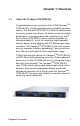
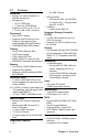
Table Of Contents
- Chapter1Overview.pdf
- Chapter2Setting Up.pdf
- CPU socket
- Chapter 2: Setting Up
- 2.0.1 Before You Begin
- 2.0.2 Work Area
- 2.0.3 Tools
- 2.0.4 Precautions
- 2.1 Rack Mounting
- 2.1.1 Installing the Server in a Rack
- 1. Screw the mounting ear to each side of Transport GT20 as shown using 2 screws from the supplied screws kit.
- 2. Draw out the inner rails from rail assembly. Install inner rails to left and right sides of chassis using 2 M4-5L(D) screws for each side.
- 3. Measure the distance between inner side of the front and rear mounting brackets in the rack.
- 4. Locate the front and rear brackets.
- 5. Reserve 90mm for Transport GT20 on the front bracket. Secure the front bracket to outer rail with 2 M4-4L(C) screws.
- 6. Reserve the distance same as in Step 2 on rear bracket. Secure the rear bracket to outer rail with 2 M4-4L(C) screws.
- 7. Secure the outer rail to the rack using 2 brackets and 4 M4-8L(E) screws for each side (A). Secure the mounting brackets from inside, not outside, of the rack (B).
- 8. Draw out the middle rail to the latch position.
- 9. Lift the chassis and then insert the inner slide rails into the middle rails.
- 10. Push the chassis in and press the latch key (A). Then push the whole system into the rack (B).
- 11. Secure the mounting ears of chassis to the rack with 2 M4-15L(F) screws.
- 2.1.1 Installing the Server in a Rack
- 2.2 Installing Motherboard Components
- 2.2.1 Removing the Chassis Cover
- 2.2.2 Installing the CPU, Heatsink and Air Duct
- 1. Release the pre-installed air duct. Locate the CPU socket.
- 2. Remove the cover on the CPU socket.
- 3. Locate the lever of CPU socket.
- 4. Press and pull the lever in the direction as illustrated..
- 5. Open the socket in the direction as illustrated.
- 6. Place CPU on the socket, ensuring that the edge with triangle mark aims at the edge of socket with triangle mark.
- 7. Close the cover and secure the CPU socket in the reverse procedures from step 2 to 6.
- 8. Secure the heatsink with 4 screws. NOTE: Remember to install the washer and nut while installing the screws.
- 9. Secure the air duct with 2 screws.
- 2.2.3 Installing the Memory
- 1. Locate the memory slots on the motherboard.
- 2. Press the memory slot locking levers in the direction of the arrows as shown in the following illustration.
- 3. Align the memory module with the slot. The module has indentations that align with notches in the slots.
- 4. Insert the memory module into the slot as shown.
- 2.2.4 Installing the PCI Card
- 1. Push the tab of PCI slot on the rear panel in the direction as shown to release the bracket.
- 2. Move the bracket to right as shown and then take off the bracket (A).
- 3. Insert the PCI card in the directions of arrow (B).
- 4. Push the tab of PCI slot on the rear panel in the direction as shown to fix PCI card.
- 2.3 Installing the Hard Drive
- 1. Press the locking lever latch in the direction of arrow (A) and then pull the locking lever open (B).
- 2. Slide the drive tray out.
- 3. Place a hard drive into the drive tray.
- 4. Using 4 HDD screws to secure the HDD.
- 5. Reinsert the drive tray into the chassis (A), ensuring that the drive tray is completely inserted into the chassis (B).
- 6. Pressing the locking lever to secure the hard drive tray.
- 2.4 Installing the Slim FDD (Option)
- 1. Locate the two FDD rails and screws from the FDD kit. Secure the two rails to FDD using four screws.
- 2. Connect the FFC cable to FDD.
- 3. Use a screw driver to take off the door of FDD tray.
- 4. Insert the FDD module into the tray.
- 5. Connect the FFC cable to the FDD connector on M1012 adapter board.
- 6. Locate the FDD cable from FDD kit. Connect the wrinkle side to the connector on M1012 adapter board. Refer to the picture below for the correct direction.
- 7. Connect the other side to the connector on motherboard.
- Chapter3Replacing.pdf
- Chapter 3: Replacing Pre-Installed Components
- 3.1 Introduction
- 3.2 Disassembly Flowchart
- 3.3 Removing the Cover
- 3.4 Replacing Motherboard Components
- 3.5 Replacing the LED Control Board
- 1. Remove the 2 screws securing the LED control board to the chassis.
- 2. Pull the LED control board free from the chassis and unplug the ribbon and USB cables from the connector.
- 3. Remove the three screws securing the LED control board to the bracket
- 4. Release the LED control board from the chassis. After replacement, insert and secure the unit to the chassis following the reverse procedures from step 1~3.
- 3.6 Replacing the M1012 Adapter Board
- 1. Before replacing M1012 adapter board, you must disconnect the four SATA cables connected to the SATA backplane. After that, disconnect all the cables connected to the M1012 adapter board.
- 2. Remove the Front Panel, LAN/ID LED and Fan Tach cables.
- 3. Remove the Front Panel Control Board cable.
- 4. Remove one power cable connected to M1012 adapter board and two power cables connected to SATA backplane.
- 5. Remove the 6 screws securing the M1012 adapter board. After that, you can release the M1012 adapter board from the chassis.
- 3.6.1 M1012 Adapter Board Features
- 3.6.2 M1012 Adapter Board Connector Pin Definition
- 3.6.3 System Fan Layout
- 3.7 Replacing the SATA Backplane
- 1. After removing the M1012 adapter board, you can easily grab the two lables to lift the SATA backplane.
- 2. Remove the ten screws that secure the bracket to the backplane.
- 3. Release the backplane free from the bracket.
- 4. Replace the unit to the chassis following the reverse procedures from step 1 to 3 after done.
- 3.7.1 S-ATA Backplane (M1204) Features
- 3.8 Replacing the Cooling Fan
- 3.9 Replacing the Power Supply
- Chapter 3: Replacing Pre-Installed Components
- Appendix.pdf
- Appendix I: BIOS Differences
- Appendix II: Cable Connection Tables
- Table 1: B5161G20S4H Model
- Table 2: System Fan to M1012 Adapter Board
- Table 3: M1012 Adapter Board to Motherboard
- Table 4: Power Supply to Motherboard
- Table 5: Power Supply to M1012 Adapter Board
- Table 6: Power Supply to M1204 Backplane
- Table 7: M1012 Adapter Board to Motherboard
- Table 8: M1003 Front Panel Control Board Related Cable
- Table 9: CD-ROM Related Cable
- Table 10: Chassis Intrusion Cable
- Table 11: FDD Related Cable (Option)
- Technical Support
- Appendix III.pdf
- Appendix III: Installing SMDC Cards
- Installing M3289 into HDD Tray
- 1. Fold up the cable.
- 2. a: Choose a HDD tray. b: Insert the cable into the rear of HDD tray. c: Pull the cable out.
- 3. Connect the cable to M3289.
- 4. Align M3289 in reverse with 4 “M1” stand-offs. Secure the SMDC with 4 screws as illustrated.
- 5. Secure M3289 onto HDD tray as illustrated.
- 6. Insert and secure the HDD tray. NOTE: For internal or dummy HDD tray, secure the HDD tray with 1 or 2 screws.
- 7. Arrange and connect the cable to SMDC connector on mainboard. Be careful not to block the air flow.
- Installing M3290/M3291 into HDD tray
- 1. Secure a removable stand-off of 13.5mm to the location of “M2” stand-off as illustrated on SMDC bracket.
- 2. Secure M3290 in reverse to 4 “M2” stand-offs on bracket.
- 3. a: Choose a HDD tray. NOTE: Refer to the location of SMDC connector on mainboard for choosing a HDD tray. b: Secure SMDC to the HDD tray.
- 4. a: Inset the cable into the rear of HDD tray. b: Connect the cable to M3290. c: Insert and secure HDD tray.
- 5. Arrange and connect the cable to SMDC connector on mainboard. Be careful not to block the air flow.
- Installing M3290/M3291 into GT24 Chassis
- 1. Disconnect the power connectors on HDD backplane and M1010.
- 2. Push the power cables aside.
- 3. Align M3290 with 4 “M2” PC stand-offs. Secure M3290 to mainboard with 4 screws.
- 4. Connect the cable to M3290. Arrange and connect the cable to SMDC connector on mainboard. Be careful not to block the air flow.
- 5. Reconnect the power connectors on HDD backplane and M1010.
- Installing M3289 into HDD Tray
- Appendix III: Installing SMDC Cards
- Appendix.pdf
- Appendix I: BIOS Differences
- Appendix II: Cable Connection Tables
- Table 1: B5161G20S4H Model
- Table 2: System Fan to M1012 Adapter Board
- Table 3: M1012 Adapter Board to Motherboard
- Table 4: Power Supply to Motherboard
- Table 5: Power Supply to M1012 Adapter Board
- Table 6: Power Supply to M1204 Backplane
- Table 7: M1012 Adapter Board to Motherboard
- Table 8: M1003 Front Panel Control Board Related Cable
- Table 9: CD-ROM Related Cable
- Table 10: Chassis Intrusion Cable
- Table 11: FDD Related Cable (Option)
- Appendix III.pdf
- Appendix III: Installing SMDC Cards
- Installing M3289 into HDD Tray
- 1. Fold up the cable.
- 2. a: Choose a HDD tray. b: Insert the cable into the rear of HDD tray. c: Pull the cable out.
- 3. Connect the cable to M3289.
- 4. Align M3289 in reverse with 4 “M1” stand-offs. Secure the SMDC with 4 screws as illustrated.
- 5. Secure M3289 onto HDD tray as illustrated.
- 6. Insert and secure the HDD tray. NOTE: For internal or dummy HDD tray, secure the HDD tray with 1 or 2 screws.
- 7. Arrange and connect the cable to SMDC connector on mainboard. Be careful not to block the air flow.
- Installing M3290/M3291 into HDD tray
- 1. Secure a removable stand-off of 13.5mm to the location of “M2” stand-off as illustrated on SMDC bracket.
- 2. Secure M3290 in reverse to 4 “M2” stand-offs on bracket.
- 3. a: Choose a HDD tray. NOTE: Refer to the location of SMDC connector on mainboard for choosing a HDD tray. b: Secure SMDC to the HDD tray.
- 4. a: Inset the cable into the rear of HDD tray. b: Connect the cable to M3290. c: Insert and secure HDD tray.
- 5. Arrange and connect the cable to SMDC connector on mainboard. Be careful not to block the air flow.
- Installing M3290/M3291 into GT24 Chassis
- 1. Disconnect the power connectors on HDD backplane and M1010.
- 2. Push the power cables aside.
- 3. Align M3290 with 4 “M2” PC stand-offs. Secure M3290 to mainboard with 4 screws.
- 4. Connect the cable to M3290. Arrange and connect the cable to SMDC connector on mainboard. Be careful not to block the air flow.
- 5. Reconnect the power connectors on HDD backplane and M1010.
- Installing M3289 into HDD Tray
- Appendix III: Installing SMDC Cards
- Appendix III.pdf
- Appendix III: Installing SMDC Cards
- Installing M3289 into HDD Tray
- 1. Fold up the cable.
- 2. a: Choose a HDD tray. b: Insert the cable into the rear of HDD tray. c: Pull the cable out.
- 3. Connect the cable to M3289.
- 4. Align M3289 in reverse with 4 “M1” stand-offs. Secure the SMDC with 4 screws as illustrated.
- 5. Secure M3289 onto HDD tray as illustrated.
- 6. Insert and secure the HDD tray. NOTE: For internal or dummy HDD tray, secure the HDD tray with 1 or 2 screws.
- 7. Arrange and connect the cable to SMDC connector on mainboard. Be careful not to block the air flow.
- Installing M3290/M3291 into HDD tray
- 1. Secure a removable stand-off of 13.5mm to the location of “M2” stand-off as illustrated on SMDC bracket.
- 2. Secure M3290 in reverse to 4 “M2” stand-offs on bracket.
- 3. a: Choose a HDD tray. NOTE: Refer to the location of SMDC connector on mainboard for choosing a HDD tray. b: Secure SMDC to the HDD tray.
- 4. a: Inset the cable into the rear of HDD tray. b: Connect the cable to M3290. c: Insert and secure HDD tray.
- 5. Arrange and connect the cable to SMDC connector on mainboard. Be careful not to block the air flow.
- Installing M3290/M3291 into GT24 Chassis
- 1. Disconnect the power connectors on HDD backplane and M1010.
- 2. Push the power cables aside.
- 3. Align M3290 with 4 “M2” PC stand-offs. Secure M3290 to mainboard with 4 screws.
- 4. Connect the cable to M3290. Arrange and connect the cable to SMDC connector on mainboard. Be careful not to block the air flow.
- 5. Reconnect the power connectors on HDD backplane and M1010.
- Technical Support
- Installing M3289 into HDD Tray
- Appendix III: Installing SMDC Cards
PREFACE
Copyright
This publication, including all photographs, illustrations, and soft-
ware, is protected under international copyright laws, with all rights
reserved. Neither this manual, nor any material contained herein,
may be reproduced without written consent of the manufacturer-.
Copyright 2006
Version 1.0
Disclaimer
Information contained in this document is furnished by TYAN Com-
puter Corporation and has been reviewed for accuracy and reliability
prior to printing. TYAN assumes no liability whatsoever, and dis-
claims any express or implied warranty, relating to sale and/or use of
TYAN products including liability or warranties relating to fitness for
a particular purpose or merchantability. TYAN retains the right to
make changes to product descriptions and/or specifications at any
time, without notice. In no event will TYAN be held liable for any
direct or indirect, incidental or consequential damage, loss of use,
loss of data or other malady resulting from errors or inaccuracies of
information contained in this document.
Trademark Recognition
All registered and unregistered trademarks and company names
contained in this manual are property of their respective owners
including, but not limited to the following.
TYAN and Transport GT20 B5161 are trademarks of TYAN Com-
puter Corporation.
Intel, Prescott, and combinations thereof are trademarks of Intel
Corporation.
Phoenix, PhoenixBIO are trademarks of Phoenix Technologies.
Microsoft Windows is a trademark of Microsoft Corporation.
IBM, PC, AT, PS/2 are trademarks of IBM Corporation.
Portable Document Format (PDF) is a trademark of Adobe Corpora-
tion.