Tyan S1598 Trinity ATX Motherboard User’s Manual Revision 1.00 Copyright © Tyan Computer Corporation, 1999. All rights reserved. No part of this manual may be reproduced or translated without prior written consent from Tyan Computer Corp. All registered and unregistered trademarks and company names contained in this manual are propery of their respective companies including, but not limited to the following. AwardBIOS is a trademark of Award Software Inc. Windows is a trademark of Microsoft Corporation.
Table of Contents 1. Introduction.....................................................................................................4 Overview..................................................................................................... 4 Icons............................................................................................................5 Hardware Specifications/Features.......................................................... 5 Software Specifications.................................
This page has been intentionally left blank.
Chapter 1 chapter 1 Introduction Introduction Overview The S1598 Trinity ATX is a quality, high performance mainboard designed for Socket 7 microprocessors. This mainboard utilizes the VIA MVP3 100MHz AGPset and host bus speeds of 66MHz to 100MHz. For CPU speed support, please refer to the CPU Compatibility Chart in Tyan’s website (http://www.tyan.com/support/html/socket_7_compatibility.html).
Icons In order to help you navigate this manual and set up your system, we have added several icons to our format. This icon alerts you to particularly important details regarding the setup or maintenance of your system. This icon often appears next to information that may keep you from damaging your board or important! system. While we will often point out the most vital paragraphs in a chapter, you should always read every word in the text. Failing to do so can lead to exasperation and expense.
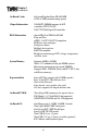
Chapter 1 Introduction On Board Cache •On board Pipeline Burst SRAM 1MB •512K or 2MB (manufacturing option) Chipset Information •VIA MVP3 100MHz memory & AGP controller(VT82C598AT) •VIA VT82C686 Super I/O controller BIOS Information •Award BIOS on 2MB flash RAM •Plug and Play •APM 1.2 / ACPI 1.0 / PC98 compliant •IDE drive auto configure •Soft power-down •Multiple boot options •DMI 2.
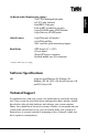
Other Features •3-pin Wake on LAN header* •3-pin Wake on Ring •Two 3-pin Fan speed monitoring support Form Factor •ATX design (8.3” x 12.0”) •4 Layer board •20-pin ATX power connector •Stacked (double row) I/O connectors * Requires ATX 2.01 power supply Software Specifications OS •Operates with Windows 95, Windows 98, Windows NT 4.0, OS/2 v4.0, Novell Netware v5.0, and SCO Unix v5.05 Technical Support If a problem arises with your system, you should turn to your dealer for help first.
Chapter 1 Introduction Help resources: 1. See FAQ and beep codes sections of this manual. 2. See Tyan web site for FAQ, bulletins, driver updates, etc. http://www.tyan.com 3. Contact your dealer or distributor for help BEFORE calling Tyan. 4. Email Tyan tech support: techsupport@tyan.com 5. Call Tyan tech support: 510-440-8808 Returning Merchandise for Service During the warranty period, contact your distributor or system vendor FIRST for any product problems.
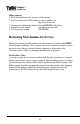
chapter 2 INSTALL Board Installation Unpacking The mainboard package should contain the following: (1) S1598 mainboard (1) 40-pin IDE and 34-pin floppy cable pack (1) S1598 User’s Manual (1) Driver CD Precautions What’s the first thing I should do? The first thing you should do is read this user’s manual. It contains important information which will make configuration and setup much easier.
Chapter 2 Board Installation ! important! and then touch any metal part on the computer case. (Or wear a grounded wrist strap.) (2) Hold the motherboard by its edges and do not touch the bottom of the board. (3) Avoid touching motherboard components, IC chips, connectors, and leads. (4) Avoid touching pins of memory modules and chips. (5) Place motherboard on a grounded antistatic surface or on the antistatic bag.
6. Connect Power Supply 7. Install Add-on Cards 8. Connect PS/2, USB, Serial and Parallel Devices What is a Jumper? Jumpers and pins are connected by slipping the blue plastic jumper connector overtop of two adjacent jumper pins (indicated by 1-2 or 2-3). The metal rod inside the plastic shell bridges the gap between the two pins, completing the circuit. See Figure 2-2 for more examples of pin connections.
Chapter 2 Board Installation Map of Motherboard Jumpers ATX power connector Kbrd Mouse JP4 JP5 JP6 JP7 JP1 JP2 JP3 1 USB Socket 7 DIMM bank 1 DIMM bank 2 DIMM bank 3 Com 1 Mic in Primary IDE connector Line in JP8 JP9 JP10 JP11 JP12 VIA MVP3 chipset Speaker Joystick (Audio optional) Com 2 Floppy drive connector Fan1 Secondary IDE connector Parallel AGP port CD In 1 Video 1 PCI slot 1 PCI slot 2 Fan2 WOL 1 PCI slot 3 USB3 USB2 JP13 VIA MVP3 chipset 3 volt lithium battery WOR 1
Picture of Motherboard Features PS/2 mouse 3 DIMM slots ATX power connector 1MB L2 cache CPU temperature sensor ZIF Socket 7 INSTALL PS/2 Keyboard USB header VIA MVP3 AGP port 5 PCI slots 2 ISA slots S1598 Trinity ATX 13 Award BIOS
Chapter 2 Board Installation 1. Setting Jumpers 1-A. CPU Bus Speed Settings 1-B. CPU Clock Multiplier Bus Spe e d JP4 JP5 JP6 M ultiplie r JP1 JP2 JP3 60M Hz 2- 3 2- 3 2- 3 2.5x ON ON O FF 66M Hz 1- 2 2- 3 2- 3 3x O FF ON O FF 75M Hz 1- 2 1- 2 2- 3 3.5x O FF O FF O FF O FF ON 83M Hz 1- 2 2- 3 1- 2 4x ON 95M Hz 2- 3 1- 2 1- 2 4.5x ON ON ON 100M Hz 1- 2 1- 2 1- 2 5x O FF ON ON 5.5x O FF O FF ON 1-C.
5 6 Power On/Off Switch 7 8 Ground VCC 9 10 Ground Receive 11 12 K/B Lock IRRX 13 14 Ground Ground 15 16 SM I Switch IRTX 17 18 Ground Pwr/Slp LEDs Ground Pin1 Pin2 Pin18 Power Switch 4 Ground Pin17 SMI Switch HDD LED 2 Power LED 3 Infrared 1 LED INSTALL VCC Reset Switch 1-D. J3 External Pin Assignments J3 Side View 1-E. FAN Pin Assignments FAN1, FAN2 1 2 3 GND +12V Fan Monitor 1-F.
Chapter 2 Board Installation ACPI Bi-Color LED Connector (J5) This connector provides a bi-color (green / yellow) LED for your computer chassis. When the computer system is On, the Green LED will light up. If the system is on stand-by mode, the Yellow LED will light up. Whenever there is an incoming message, the LED will flash on and off. Soft Power Connector The Soft Power Connector is located on pins 6 and 8 of jumper block J3. Pressing the Soft Power Button will turn the sytem on and off.
3. Installing Memory Since TYAN boards are manufactured with performance in mind, you should use add-in components that match. Some DIMM modules may seem to be high quality because of name or feel but that does not guarantee real-world usability. Some cheaper or OEM memory may have brand-name components, but they may contain inferior or substandard parts which do not meet the critical tolerances our products require.
Chapter 2 Board Installation Figure 2-3 *The image above is used to illustrate a concept and may not represent the actual image of your motherboard. To install your DIMMs, line your module up so that the pins fit into the slot. There is only one way that your DIMM can fit properly. Make sure that the short row of pins is lined up with the short gap in the DIMM slot. Figure 2-3 above shows how to sit the DIMM into its slot.
INSTALL Figure 2-4 *The image above is used to illustrate a concept and may not represent the actual image of your motherboard. Some details of memory installation: • The mainboard supports 32MB, 64MB, 128MB SDRAM modules. • PC-100 DIMMs are required if CPU bus speed is at 100MHz • SDRAM, Parity, and ECC (using Parity memory) memory is supported. Unbuffered RFU Buffered 168-pin DIMM Figure 2-5 Cache Memory The Trinity ATX has 1MB (or 2MB) of onboard pipeline burst SRAM. This SRAM cannot be upgraded.
Chapter 2 Board Installation 4. Installing the CPU and Cooling Fan Socket 7 processors (see Specifications on page 5) can be used on the Trinity ATX. Please refer to page 14 for the correct CPU jumper settings for your CPU. Remember: • The CPU is a sensitive electronic component and it can easily be damaged by static electricity. Do not touch the CPU pins with your fingers. • Before the CPU is installed, the mainboard must be placed on a flat surface.
INSTALL Figure 2-8 Locate the cooling fan connector (e.g. CPU Fan, Fan1) on the motherboard. Plug the CPU’s cooling fan cable into the cooling fan connector on the board. There will be a plastic clip assembly similar to that of the ATX power connector that will force you to connect the fan cable correctly (see Figure 2-8 above).
Chapter 2 Board Installation 5. Connecting IDE and Floppy Drives The colored stripe on a ribbon cable should face toward the keyboard connector. In Figure 2-9 on the previous page, you can see how the IDE cables should look when they are connected to your hard drive. Notice how Pin 1 (denoted by a red stripe) is connected so that it is next to the power connector of the drive. The primary IDE connector is black; the secondary IDE connector is white.
Figure 2-11 INSTALL Connecting Floppy Drives Pin 1 on the floppy cable is usually denoted by a red or colored stripe down one side of the cable (see Figure 2-11 on the following page). Most of the current floppy drives on the market require that the colored stripe be positioned so that it is right next to the power connector. In most cases, there will be a key pin on the cable which will force you to connect the cable properly. Drive A: is usually attached to the end of the cable with the twist in it.
Chapter 2 Board Installation Figure 2-12 Figure 2-13 Figure 2-13. Make absolutely certain that you do not miss any pins, because if you do you will void your warranty and cause damage to yourself or your motherboard when you turn the system on. After connecting the power, make sure the connector is seated firmly into its socket so it will not become loose or fall off when the computer is jostled or moved. Note: Tyan recommends using one that conforms to industry standard revision 2.01. 7.
you do this. When plugging the card in, especially when installing long cards, try to push the entire card in at one time. Don’t force one end of the card into the socket first and then the other. This will create a rocking motion between the card and the slot and it will damage the pins within the socket. • Make sure that the cards are seated securely into the slots. • Before turning on the system, make sure no cards are touching.
Chapter 2 Board Installation joystick port. It is fast enough to support video transfer, and is capable of supporting up to 127 daisy-chained peripheral devices. Connecting Com and Printer Ports warning Warning: When plugging in your keyboard and mouse, or when plugging anything into a serial or Com port, make sure that the power is off. Connecting these devices and ports while the power is on is called “hot plugging,” and may damage your system.
with the mere 132MB/s (at 33MHz bus speed) that you get with the PCI bus. Q: Does my operating system support AGP? A: Currently, only Windows 98 and Windows NT 5.0 will have built-in support for AGP. Some AGP cards require Windows 95 OSR2.1 or a special driver from Intel. Please check with your graphics vendor for more details. Q: How do I identify Pin #1 of a 3-pin jumper? A: There should be a small numeral 1 silkscreened on the board in white next to pin 1.
Chapter 2 Board Installation The "viareg" folder is for "VIA Power Management Controller" and "VIA PCI to USB Universal Host Controller". NOTE: this driver is for Win95 users. There are no drivers for WinNT 4.0. No need to install for Win98 users. The "virq13 or virq11" folder will install "VIA PCI IRQ Routing Miniport Driver". NOTE: Enable "OnChip USB" in BIOS Chipset Features setup menu and Enable "Assign IRQ for USB" in PNP/PCP Configuration Setup menu.
INSTALL This page intentionally left blank.
Chapter 3 chapter 3 BIOS Configuration BIOS Configuration Introduction to Setup This manual describes the Award EliteBIOS Setup program. The Setup program lets you modify basic system configuration settings. The settings are then stored in a dedicated battery-backed memory, called CMOS RAM, that retains the information when the power is turned off. The EliteBIOS in your computer is a customized version of an industrystandard BIOS for IBM PC AT–compatible personal computers.
the process of checking out the system and configuring it through the poweron self test (POST). When these preliminaries are finished, the BIOS seeks an operating system on one of the data storage devices (hard drive, floppy drive, etc.). The BIOS launches the operating system and hands control of system operations to it. During POST, you can start the Setup program in one of two ways: 1. By pressing immediately after switching the system on, or 2.
Chapter 3 BIOS Configuration Ke y Up arrow Function Move to previous item. Down arrow Move to next item. Left arrow Right arrow Esc key Move to iten on the left hand. Move to item on the right hand. Main Menu: Quit and do not save changes into CMOS RAM. Status Page Setup Menu: Exit current page and return to Main Menu. PgUp key Increase the numeric value or make changes. PgDn key Decrease the numeric value or make changes. + key Increase the numeric value or make changes.
Setup Variations Not all systems have the same Setup. While the basic look and function of the Setup program remains the same for all systems, the appearance of your Setup screens may differ from the screens shown here. Each system design and chipset combination require custom configurations. In addition, the final appearance of the Setup program depends on your system designer.
Chapter 3 BIOS Configuration Standard CMOS Setup Options in the original PC AT-compatible BIOS. BIOS Features Setup Award Software enhanced BIOS options. Chipset Features Setup Options specific to your system chipset. Power Management Setup Advanced Power Management (APM) options. PnP/PCI Configuration Plug and Play standard and PCI Local Bus configuration options. Integrated Peripherals I/O subsystems that depend on the integrated peripherals controller in your system.
Standard CMOS Setup In the Standard CMOS menu you can set the system clock and calendar, record disk drive parameters and the video subsystem type, and select the type of errors that stop the BIOS POST. Date The BIOS determines the day of the week from the other date information. This ROM PCI/ISA BIOS (2A5LET59) STANDARD CMOS SETUP AWARD SOFTWARE, INC.
Chapter 3 BIOS Configuration hard drive types, such as SCSI drives. Note: We recommend that you select type auto for all drives. The BIOS can automatically detect the specifications and optimal operating mode of almost all IDE hard drives. When you select type auto for a hard drive, the BIOS detects its specifications during POST, every time the system boots. If you do not want to select drive type auto, other methods of selecting the drive type are available: 1.
Drive A, Drive B Select the correct specifications for the diskette drive(s) installed in the computer. N one N o diskette drive installed 360K , 5.25 in 5- 1/4 inch PC- type standard drive; 360 kilobyte capacity 1.2M, 5.25 in 5- 1/4 inch AT- type high- density drive; 1.2 megabyte capacity 720K , 3.5 in 3- 1/2 inch double- sided drive; 720 kilobyte capacity 1.44M, 3.5 in 3- 1/2 inch double- sided drive; 1.44 megabyte capacity 2.88M, 3.5 in 3- 1/2 inch double- sided drive; 2.
Chapter 3 BIOS Configuration Memory You cannot change any values in the Memory fields; they are only for your information. The fields show the total installed random access memory (RAM) and amounts allocated to base memory, extended memory, and other (high) memory. RAM is counted in kilobytes (KB: approximately one thousand bytes) and megabytes (MB: approximately one million bytes).
ROM PCI/ISA BIOS (2A5LET59) BIOS FEATURES SETUP AWARD SOFTWARE, INC.
Chapter 3 BIOS Configuration Settings Chart (Continued) Setting Option BIOS Default Setup Default D4000-D7FFF Shadow Disabled Disabled D8000-DBFFF Shadow Disabled Disabled DC000-DFFFF Shadow Disabled Disabled Cyrix 6x86 / MII CPU ID Enabled Enabled Virus Warning When enabled, you receive a warning message if a program (specifically, a virus) attempts to write to the boot sector or the partition table of the hard disk drive. You should then run an anti-virus program.
Enabled assigns physical drive B to logical drive A, and physical drive A to logical drive B. Boot Up Floppy Seek When Enabled, the BIOS tests (seeks) floppy drives to determine whether they have 40 or 80 tracks. Only 360-KB floppy drives have 40 tracks; drives with 720 KB, 1.2 MB, and 1.44 MB capacity all have 80 tracks. Because very few modern PCs have 40-track floppy drives, we recommend that you set this field to Disabled to save time.
Chapter 3 BIOS Configuration Security Option If you have set a password, select whether the password is required every time the System boots, or only when you enter Setup. PCI/VGA Palette Snoop Your BIOS Setup many not contain this field. If the field is present, leave at Disabled. OS Select for DRAM > 64MB Select OS2 only if you are running OS/2 operating system with greater than 64 MB of RAM on your system.
Chipset Features Setup This section describes features of the Intel 440EX chipset. Advanced Options The parameters in this screen are for system designers, service personnel, and technically competent users only. Do not reset these values unless you understand the consequences of your changes. Note: This chapter describes all fields offered by Award Software in this screen. Your system board designer may omit or modify some fields.
Chapter 3 BIOS Configuration Chipset Features Setup - Default Settings Chart Setting Option BIOS Default Setup Default Bank 0/1 DRAM Timing SDRAM 10ns SDRAM 10ns Bank 2/3 DRAM Timing FP/EDO 70ns FP/EDO 70ns Bank 4/5 DRAM Timing FP/EDO 70ns FP/EDO 70ns SDRAM Cycle Length 3 3 DRAM Read Pipeline Disabled Enabled Cache Rd+CPU Wt Pipeline Disabled Enabled Cache Timing Fast Fast Video BIOS Cacheable Disabled Enabled System BIOS Cacheable Disabled Enabled Memory Hole At 15Mb Addr Di
Cache Timing For a secondary cache of one bank, select Faster. For a secondary cache of two banks, select Fastest. Video BIOS Cacheable Selecting Enabled allows caching of the video BIOS ROM at C0000h to C7FFFh, resulting in better video performance. However, if any program writes to this memory area, a memory access error may result in a system error. System BIOS Cacheable If Enabled, results in better system performance by permitting caching of the system BIOS ROM at F0000h-FFFFFh.
Chapter 3 BIOS Configuration Power Management Setup Note: This chapter describes all fields offered by Award Software in this screen. Your system board designer may omit or modify some fields. ROM PCI/ISA BIOS (2A5LET5A) POWER MANAGEMENT SETUP AWARD SOFTWARE, INC.
Settings Chart (Continued) Setting Option BIOS Default Setup Default Modem Ring Resume Disabled Disabled RTC Alarm Resume Disabled Disabled Primary INTR ON ON IRQ3 (COM2) Primary Primary IRQ4 (COM1) Primary Primary IRQ5 (LPT2) Primary Primary IRQ6 (Floppy Disk) Primary Primary Primary Primary IRQ8 (RTC Alarm) Disabled Disabled IRQ9 (IRQ2 Redir) Secondary Secondary IRQ10 (Reserved) Secondary Secondary IRQ11 (Reserved) Secondary Secondary IRQ12 (PS/2 Mouse) Primary Prim
Chapter 3 BIOS Configuration Video Off Option Selects the power-saving modes during which the monitor goes blank. Always On Monitor remains on during power- saving modes. Suspend - - > Off Monitor blanked when system enters Suspend mode. All Modes- - > Off Monitor blanked when system enters any power- saving mode. Video Off Method Determines the manner in which the monitor is blanked. The Blank Screen option will let the system BIOS blank the screen when disabling video.
Doze Mode After the selected period of system inactivity (1 minute to 1 hour), the CPU clock runs at slower speed while all other devices still operate at full speed. Suspend Mode After the selected period of system inactivity (1 minute to 1 hour), all devices except the CPU shut off. ** PM Events ** A power management (PM) event awakens the system from, or resets activity timers for, Suspend mode. You can disable monitoring of common interrupt requests so they do not generate PM events.
Chapter 3 BIOS Configuration Primary Secondary The system wakes up fully when it detects IRQ activity. The system does not wake up, but the interrupt request is processed. Secondary interrupts are typically housekeeping devices needed to maintain the system while not requiring the use of the rest of the system resources. For example, IRQ8, the RTC Alarm, is configured as Secondary by default. Another example might be a network adapter continually polled by the network.
PnP/PCI Configuration Note: This chapter describes all fields offered by Award Software in this screen. Your system board designer may omit or modify some fields. ROM PCI/ISA BIOS (2A5LET5A) PNP/PCI CONFIGURATION AWARD SOFTWARE, INC.
Chapter 3 BIOS Configuration Settings Chart (continued) Setting Option BIOS Default Setup Default DMA-1 assigned to PCI / ISA PnP PCI / ISA PnP DMA-3 assigned to PCI / ISA PnP PCI / ISA PnP DMA-5 assigned to PCI / ISA PnP PCI / ISA PnP DMA-6 assigned to PCI / ISA PnP PCI / ISA PnP DMA-7 assigned to PCI / ISA PnP PCI / ISA PnP CPU to PCI Write Buffer Enabled Enabled PCI Dynamic Bursting Disabled Enabled PCI Master 0 WS Write Enabled Enabled PCI Delay Transaction Disabled Enabled
IRQ-n Assigned to When resources are controlled manually, assign each system interrupt as one of the following types, depending on the type of device using the interrupt: Legacy ISA: Devices compliant with the original PC AT bus specification, requiring a specific interrupt (such as IRQ4 for serial port 1). PCI/ISA PnP: Devices compliant with the Plug and Play standard, whether designed for PCI or ISA bus architecture.
Chapter 3 BIOS Configuration AGP Master 1 WS Write Select Enabled to add one clock tick to AGP write operations. AGP Master 1 WS Read Select Enabled to add one clock tick to AGP read operations. Assign IRQ for USB Assign an IRQ number to the onboard USB port. Assign IRQ for VGA Assign an IRQ number to your VGA adapter. Slot 1-5 IRQ for VGA This option allows a user to assign specific IRQ’s to the PCI Slot.
Integrated Peripherals - Default Settings Chart Setting Option BIOS Default Setup Default OnChip IDE First Channel Enabled Enabled OnChip IDE Second Channel Enabled Enabled IDE Prefetch Mode Disabled Enabled IDE HDD Block Mode Disabled Enabled IDE Primary Master PIO Auto Auto IDE Primary Slave PIO Auto Auto IDE Secondary Master PIO Auto Auto IDE Secondary Slave PIO Auto Auto IDE Primary Master UDMA Disabled Auto Disabled Auto IDE Secondary Master UDMA Disabled Auto IDE Sec
Chapter 3 BIOS Configuration supports. Modes 0 through 4 provide successively increased performance. In Auto mode, the system automatically determines the best mode for each device. IDE Primary/Secondary Master/Slave UDMA UDMA (Ultra DMA) is a DMA data transfer protocol that utilizes ATA commands and the ATA bus to allow DMA commands to transfer data at a maximum burst rate of 33 MB/s.
User Password When you select this function, a message appears at the center of the screen: ENTER PASSWORD: Type the password, up to eight characters, and press Enter. Typing a password clears any previously entered password from CMOS memory. Now the message changes: CONFIRM PASSWORD: In the Security Option item in the BIOS Features Setup screen, select System or Setup: System Enter a password each time the system boots and whenever you enter Setup. Setup Enter a password whenever you enter Setup.
Chapter 3 BIOS Configuration The FMW records (or programs) a new BIOS onto the flash memory chip. You cannot upgrade an Award BIOS to an AMI BIOS or vice-versa. Note: You should always clear your CMOS after flashing a BIOS. This will clear out any stray settings from your old BIOS which may have been carried over from the flashing process. Most problems encountered after flashing a BIOS will be solved by this simple procedure (see Hardware CMOS & Password Reset, page 33).
FLASH MEMORY WRITER V3.0 Copyright(C) 1993, AWARD SOFTWARE, INC. For VX/HX-2A59CT51 Date:4/13/98 File Name to Program: BIOS Error Message: Type in the whole file name, e.g. A61AW10.BIN, and confirm that you want to program the BIOS. The utility will then “Blank,” “Erase,” and “Program” the flash memory on the mainboard with the new BIOS file. You should choose “Yes” to save the original system BIOS to a floppy diskette before you program the new BIOS.
Chapter 4 chapter 4 System Resources System Resources POST Messages During the power-on self test (POST), the BIOS either sounds a beep code or displays a message when it detects a correctable error. Following is a list of POST messages for the ISA BIOS kernel. Specific chipset ports and BIOS extensions may include additional messages. An error message may be followed by a prompt to press F1 to continue or press DEL to enter Setup.
CMOS checksum error - Defaults loaded Checksum of CMOS is incorrect, so the system loads the default equipment configuration. A checksum error may indicate that CMOS has become corrupt. This error may have been caused by a weak battery. Check the battery and replace if necessary. CPU at nnnn Displays the running speed of the CPU. Display switch is set incorrectly. The display switch on the motherboard can be set to either monochrome or color.
Chapter 4 System Resources Keyboard is locked out - Unlock the key This message usually indicates that one or more keys have been pressed during the keyboard tests. Be sure no objects are resting on the keyboard. Memory Test : This message displays during a full memory test, counting down the memory areas being tested. Memory test fail If POST detects an error during memory testing, additional information appears giving specifics about the type and location of the memory error.
SYSTEM This page has been intentionally left blank.
Appendix 1 Appendix 1 Glossary Glossary ACPI (Advanced Configuration and Power Interface) is a power management specification that allows the operating system to control the amount of power distributed to the computer’s devices. Devices not in use can be turned off, reducing unnecessary power expenditure. AGP (Accelerated Graphics Port) is a PCI-based interface which was designed specifically for demands of 3D graphics applications.
Bandwidth refers to carrying capacity. The greater the bandwidth, the more data the bus, phone line, or other electrical path, can carry. Greater bandwidth, then, also results in greater speed. A BBS (Bulletin Board System) is a computer system with a number of modems hooked up to it which acts as a center for users to post messages and access information. The BIOS (Basic Input/Output System) program resides in the ROM chip, and provides the basic instructions for controlling your computer’s hardware.
Appendix 1 Glossary Closed and open jumpers Jumpers and jumper pins are active when they are On or Closed, and inactive when they are Off or Open. CMOS Complementary Metal-Oxide Semiconductors are chips that hold the basic start-up information for the BIOS. The COM port is another name for the serial port, which is so-called because it transmits the eight bits of a byte of data along one wire, and receives data on another single wire (that is, the data is transmitted in serial form, one bit after another).
tion about Plug and Play devices in the system BIOS. This information helps properly configure the system each time it boots. Firmware is low level software that controls the system hardware. Form factor is an industry term for the size, shape, power supply type, and external connector type of the PCB (personal computer board) or motherboard. The standard form factors are the AT and ATX, although TYAN also makes some Baby-AT boards. A Global timer is an onboard hardware timer, such as the Real Time Clock.
Appendix 1 Glossary Latency is the amount of time that one part of a system spends waiting for another part to catch up. This is most common when the system sends data out to a peripheral device, and is waiting for the peripheral to send some data back (peripherals tend to be slower than onboard system components). NVRAM ROM and EEPROM are both examples of Non-Volatile RAM, memory that holds its data without power. DRAM, in contrast, is volatile.
PnP is an acronym for Plug and Play, a design standard that has become ascendant in the industry. Plug and Play devices require little set-up to use. Novice end users can simply plug them into a computer that is running on a Plug and Play-aware operating system (such as Windows 95), and go to work. Devices and operating systems that are not Plug and Play require you to reconfigure your system each time you add or change any part of your hardware.
Appendix 1 Glossary operate normally. UltraDMA/33 is a fast version of the old DMA channel. UltraDMA is also called UltraATA. Without UltraDMA your system cannot take advantage of the higher data transmission rates of the new UltraATA hard drives. Universal Serial Bus or USB, is a versatile port. This one port type can function as a serial, parallel, mouse, keyboard, or joystick port. It is fast enough to support video transfer, and is capable of supporting up to 127 daisy-chained peripheral devices.
Notice for the USA Compliance Information Statement (Declaration of Conformity Procedure) DoC FCC Part 15: This Device complies with Part 15 of the FCC Rules. Operation is subject to the following conditions: 1) this device may not cause harmful interference, and 2) this device must accept any interference received including interference that may cause undesired operation.
Jumper Settings Quick Reference CPU Bus Speed Settings CPU Clock Multiplier Bus Spe e d JP4 JP5 JP6 M ultiplie r JP1 JP2 JP3 60M Hz 2- 3 2- 3 2- 3 2.5x ON ON O FF 66M Hz 1- 2 2- 3 2- 3 3x O FF ON O FF 75M Hz 1- 2 1- 2 2- 3 3.5x O FF O FF O FF 83M Hz 1- 2 2- 3 1- 2 4x ON O FF ON 95M Hz 2- 3 1- 2 1- 2 4.5x ON ON ON 100M Hz 1- 2 1- 2 1- 2 5x O FF ON ON 5.