É c h e l o n™ P. O . B o x 2 4 5 0 4 0 Milwaukee, WI 53224-9540 Phone: 414.354.0300 Fax: 414.354.7905 w w w . u - l i n e . c o m U S E R M P r i n t e d i n U . S . A .
U-LINE CORPORATION LIMITED WARRANTY U-Line Corporation warrants each U-Line product to be free from defects in materials and workmanship for a period of one year from the date of purchase; and warrants the sealed system (consisting of the compressor, the condenser, the evaporator, the hot gas bypass valve, the dryer and the connecting tubing) in each U-Line product to be free from defects in materials and workmanship for a period of five years from the date of purchase.
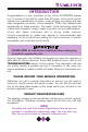
INTRODUCTION Congratulations on your purchase of the U-Line 2075DWRR drawer unit. A pioneer in the field for more than 40 years, U-Line is the world’s number one manufacturer of built-in, under-counter ice making and specialty refrigeration products. U-Line dedicates 100% of its research and development to these products. The result: U-Line technology leads the market with innovation, design, depth of product line and performance. U-Line also backs customers with a strong dealer network.
User’s Manual If you do not return your Product Registration Card, U-Line will use the date of sale to the U-Line distributor as the first date of warranty for your unit. Please also record the purchase date of your ULine unit and your dealer’s name, address and telephone number.
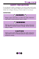
SAFETY PRECAUTIONS Do not attempt to install or operate your unit until you have read the safety precautions in this manual. Safety items throughout this manual are labeled with a Danger, Warning or Caution based on the risk type. DEFINITIONS ! DANGER ! Danger means that failure to follow this safety statement may result in severe personal injury or death. ! WARNING Warning means that failure to follow this safety statement may result in extensive product damage, serious personal injury, or death.
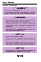
User’s Manual GENERAL PRECAUTIONS ! DANGER ! RISK OF CHILD ENTRAPMENT. Before you throw away your old refrigerator or freezer, take off the doors and leave shelves in place so that children may not easily climb inside. ! WARNING • Never attempt to repair or perform maintenance on the unit until the electricity has been disconnected.
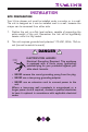
INSTALLATION SITE PREPARATION Your U-Line drawer unit must be installed under a counter or in a wall. The unit is designed so it can be installed next to a wall, because the crisper can be accessed from either side. 1. Position the unit on a flat, level surface, capable of supporting the entire weight of the unit. Remember the unit will be significantly heavier once it is fully loaded. 2. This unit requires grounded and polarized 115 VAC, 60Hz, 15A circuit (normal household current).
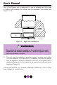
User’s Manual Your U-Line Drawer unit is designed so it can be installed next to the wall on either side because the crisper can be accessed from either side (Figure 1, 2). CABINET OR WALL DWR001 Figure 1 – Right wall installation ! WARNING The anti-tip kit must be installed on this unit before it is used. Never use the drawers as steps or a shelf to support more than the drawers’ content. 3. The unit must be installed in a wall or under a counter top to allow for the installation of the anti-tip kit.
CABINET OR WALL DWR002 Figure 2 – Left wall installation 24" MIN.
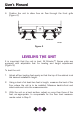
User’s Manual 4. Position the unit to allow free air flow through the front grille (Figure 4). OFF ON EXHAUST INTAKE DWR004 Figure 4 LEVELING THE UNIT It is important that the unit is level. All Échelon™ Series units are equipped with adjustable feet for leveling and height adjustment (Figure 5). To level the unit: 1. Adjust all four leveling feet evenly so that the top of the cabinet is at the desired installation height. 2.
4. Place the unit in position where it is to be installed. Re-check cabinet height and levelness (Figure 6) and adjust if necessary.
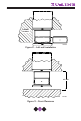
User’s Manual BUILT-IN INSTALLATION Your U-Line product is designed for built-in installation only. When built-in, it does not require additional air space for the top, sides, or rear. However, the front grille must NOT be obstructed. NOTE To ease unit installation and removal, it is recommended that the cabinet rough opening dimensions be increased by at least 1/4" over the dimensions given for your unit.
COUNTER TOP OR WALL ANTI-TIP KIT DWR010 Figure 7 CUSTOM DRAWER PANELS Two types of custom drawer panels can be installed on your U-Line unit to harmonize with or accent the surrounding decor. FULL OVERLAY DRAWER PANEL Full overlay drawer panels completely cover the drawer frames and handle to give a built-in appearance. See Table 1 for full overlay drawer panel dimensions (Figure 11, see page 13). Table 1.
User’s Manual OVERLAY PANEL KIT PARTS Part Number Description Quantity 42120 Spacer Nylon 3/8 OD x .19 ID 10 42121 Screw #10 x 5/8 Round Head 10 • The total weight of both drawer panels must not weigh more than 20 lbs. • The thickness of the drawer panel must be 3/4". Remove existing drawer front from cabinet: 1. Open drawer. Pull door gasket (Figure 8) out of the groove (top edge of door only). Start in the middle and pull outward, moving toward the edge. This may take some force. 2.
5. On a clean surface, place the wood panel face down and tape the existing drawer panel (removed in step 3) on the back of the wood panel (Figure 10) and drill the five (5) holes (5/32" drill 3/8" deep) through the coated steel panel and 3/8" into the wood panel according to the diagram (Figure 11). Remove tape from the drawer panel, and enlarge the five holes in the front panel using a .0201" drill (#7) drill.
User’s Manual 6. Attach the drawer panel to the wood panel using #10 x 5/8" (P/N 42121) wood screws and nylon spacers (P/N 42120). The nylon spacers fit between the wood panel and the drawer panel as shown (Figure 12). COATED STEEL DRAWER PANEL TYPICAL WOOD PANEL #10 X 5/8" ROUND HEAD SCREW FIVE REQUIRED PLASTIC SPACER FIVE REQUIRED DWR_OL_005 Figure 12 Drawer panel and wood panel must be aligned properly or drawer will not operate correctly. Assembling the drawer and wood panel: 7.
CUSTOM INSERT DRAWER PANEL Custom drawer panels can be inserted into the drawer frames to match the B surrounding decor. Custom drawer panels can be flat or raised, as long as the maximum panel thickness where inserted into the drawer reveal (channel) is 1/4" A thick. For raised panels, the depth of the reveal is 1/4" on all four sides. See Table 2 for custom drawer panel insert dimensions (Figure 13). A Table 2.
User’s Manual Install the custom insert as follows: ! WARNING Insert edges may be SHARP! Use care when installing. 1. Open drawer. Pull drawer gasket out of groove (top edge of drawer only). Start in the middle and pull outward, moving toward the edge (Figure 14). This may take some force, be careful. 2. Remove the three screws behind the gasket. Carefully pull the top handle up and off. You may discard the top handle as it will be replaced with the full handle. 3.
5. Slide custom drawer panel insert into 1/4" channel in drawer front. 6. Attach the full handle to the lower handle using the 3 screws removed in step 2. 7. Holding drawer gasket out of the way, replace handle on drawer making sure it is seated properly on insert and that screw holes line up. 8. Install two screws removed in step 3. 9. Starting at the corners and working inward, push drawer gasket into place on the drawer.
User’s Manual TEMPERATURE CONTROLLER 1 2 WARMER SET TEMP COOLER CLRCO011B Figure 17 The temperature controller (Figure 17) is located in the top drawer. It consists of an LED display, two LED status indicator lights and three touch pad buttons. The LED display shows the temperature set point and is calibrated in degrees Fahrenheit. The controller is factory programmed for a set point of 38°F which will show when the unit is first powered-up.
DRAWERS The drawers should only be removed for servicing by a trained and certified repair person. BIN GUIDE TOP STORAGE BIN Grasp the bin handle and slide backward to access the contents below (Figure 18). The bin may be completely removed for cleaning once it clears the guides on each side of the drawer. If heavy items are stored in bin, push front of bin down slightly while sliding. Slide bin forward, especially with heavy items, to ensure that drawer closes completely.
User’s Manual OPERATION DRAWER ORGANIZER Adjust the drawer organizer to compensate for different size bottles or items. The organizer can be used in either drawer, but is shipped from the factory in the top drawer. The organizer may be adjusted left-to-right or front-to-back as required. When adjusting the organizer, open the drawer fully, remove all items, and brace the drawer to prevent movement.
Be sure that items stored in the rear of the top drawer do not interfere with the sliding operation of the storage bin (Figure 21). Tall items such as milk jugs can be stored toward the front of the drawer as long as they do not interfere with the closing of the drawer. Taller items can be stored on their side in the storage bin. STORAGE BIN The storage bin is designed to accommodate the storage of two wine bottles, even when opened.
User’s Manual LIGHT BULB REPLACEMENT Light bulb replacement in the Échelon™ series is simple. 1. 2. Remove the light housing cover by sliding the cover toward the tab, swinging the end opposite the tab down and pulling down and away (Figure 22). 1 TAB Replace bulb with genuine U-Line #31317 replacement. 2 U-Line P/N 31317 UL305 3 Figure 22 ! WARNING Do not use any other replacement bulb than the one recommended. 3.
CLEANING & MAINTENANCE Periodic cleaning and proper maintenance will ensure efficiency, top performance, and long life. The maintenance intervals listed are based on normal conditions. You may want to shorten the intervals if you have pets, the unit is used outdoors, or other special considerations. EXTERIOR CLEANING — AS REQUIRED The door, grille and cabinet may be cleaned with a mild detergent and warm water solution. Do not use solvent based or abrasive cleaners.
User’s Manual 5. Reconnect power to the unit. ! WARNING • DO NOT use solvent cleaning agents or abrasives on the interior. These cleansers may damage or discolor the interior. CONDENSER CLEANING - EVERY 3 MONTHS ! WARNING Disconnect electric power to the unit before cleaning the condenser. To remove and replace the grille for access to the condenser fins follow this procedure: DWR019 Figure 23 1. Remove the screws (Figure 23) at each end of the grille. 2. Remove the grille.
! WARNING DO NOT touch the condenser fins. The condenser fins are SHARP and can be easily damaged. 3. Clean the condenser coil using a soft brush with a “combing” action or vacuum cleaner. Do not touch the condenser coil. 4. Position the grille to align the screw holes with the cabinet. 5. Insert the grille screws and tighten. Do not overtighten. STORAGE If the unit is to be stored or not used for extended periods: 1.
User’s Manual TROUBLESHOOTING BEFORE CALLING FOR SERVICE If the unit appears to be malfunctioning, read through NORMAL OPERATION first. If the problem persists, check the TROUBLESHOOTING GUIDE. Locate the problem in the guide and refer to the cause and its remedy before calling for service. The problem could be something very simple which can be solved without a service call.
Problem The unit is not cold enough (continued) Possible Cause Temperature not set cold enough. Remedy Set temperature controller to colder setting. See page 18. Allow 24 hours for temperature to stabilize. Noise during operation. Certain sounds are normal. Soft sounds from the compressor and fan motor will be heard. Fresh food section too cold. Drawer not closed correctly. Be sure drawer is closed correctly. Temperature control set too cold. Set temperature controller to warmer setting.
User’s Manual 28
É c h e l o n™ P. O . B o x 2 4 5 0 4 0 Milwaukee, WI 53224-9540 Phone: 414.354.0300 Fax: 414.354.7905 w w w . u - l i n e . c o m U S E R M P r i n t e d i n U . S . A . P / N 3 0 0 0 1 ( R e v .